00193437-03_AI_PowerSupplyConversion_DE+EN.pdf - 第275页
Assembly Instructions, Converting the Power Supp ly 8 Converting the power supply on the HS- XX / Di machine using PKE32/XTU-32 12/2013 Edition 8.6 Converting the power supply from 3 x 208 VAC to 3 x 400 VAC 273 8.6.6 Re…
8 Converting the power supply on the HS-XX / Di machine using PKE32/XTU-32 Assembly Instructions, Converting the Power Supply
8.6 Converting the power supply from 3 x 208 VAC to 3 x 400 VAC 12/2013 Edition
272
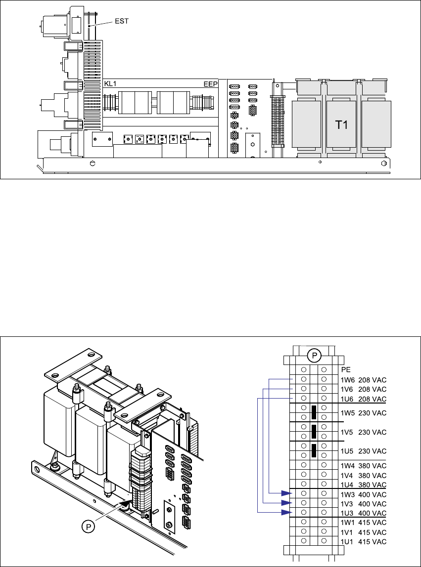
8.6.4 Overview of the parts - power supply unit - side view
Fig. 8 - 10 Overview of the parts - power supply unit - side view
EST Inrush current limiter board TG 31033-01
T1 Three-phase transformer
8.6.5 Converting the three-phase transformer T1 from 3 x 208 VAC to 3 x 400 VAC
Connect the cable from
terminal 1W6 to terminal 1W3
terminal 1V6 to terminal 1V3 and
terminal 1U6 to terminal 1U3.
Fig. 8 - 11 Primary terminals for transformer T1
Assembly Instructions, Converting the Power Supply 8 Converting the power supply on the HS-XX / Di machine using PKE32/XTU-32
12/2013 Edition 8.6 Converting the power supply from 3 x 208 VAC to 3 x 400 VAC
273
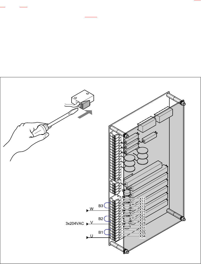
8.6.6 Reconnecting the inrush current limiter board
The inrush current limiter board is located on the back of the front panel (see item EST in Fig. 8 -
10, page 272.
Move the following jumpers (see Fig. 8 - 12):
B3 from terminal X13 to terminal X12,
B2 from terminal X23 to terminal X22 and
B1 from terminal X33 to terminal X32.
Reconnect the following wires:
(W) from terminal X14 to terminal X13,
(V) from terminal X24 to terminal X23 and
(U) from terminal X34 to terminal X33.
)
:
Fig. 8 - 12 Reconnecting the inrush current limiter board

8 Converting the power supply on the HS-XX / Di machine using PKE32/XTU-32 Assembly Instructions, Converting the Power Supply
8.7 HS-60 / D1 / D2 / D4 circuit diagrams 12/2013 Edition
274
8.6.7 Installing the power supply unit
Carefully push the power supply unit into the housing until it reaches the stop.
Use the M8 hexagon socket-head screw to secure the unit at the bottom.
Check that the yellow-green PE wire is connected to the door.
Close the door.
PLEASE NOTE: 8
Make sure that the actuating shaft of the main switch slides easily into the opening in the ro-
tary button. 8
Use the machine key to lock the door.
8.6.8 Carry out the safety check to DIN EN 60 204
When the conversion is complete, carry out a safety check to DIN EN 60 204.
Follow the procedure described in section 2, page 146 onwards.
8.7 HS-60 / D1 / D2 / D4 circuit diagrams
3 x 208 V conversion kit for HSxx/D, for USA
00119801-010102LD4, 2 sheets, see page 275
and 276 8
3 x 400 V conversion kit for HSxx/D, international
00119802-010101LD4, 2 sheets, see page 277
and 278 8