X3_X4_Series machine - 第110页
3 Technical data User manual SIPLACE X-Series 3.4 Dimensions and weight of the placement mach ine Software Version SR. 601.xx 11/2005 US Edition 110 3.4.10 Center of grav ity for the X-se ries placement mac hines 3 3 3 F…
User manual SIPLACE X-Series 3 Technical data
Software Version SR.601.xx 11/2005 US Edition 3.4 Dimensions and weight of the placement machine
109
3.4.9 Maneuvering distance for the component trolley on the X2 machine
3
3
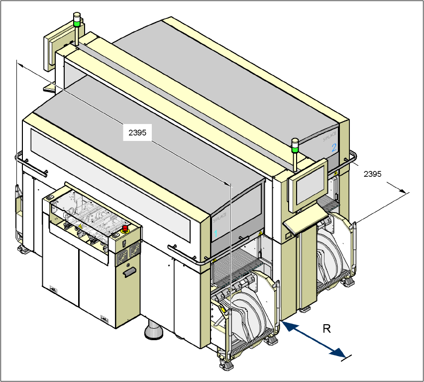
Fig. 3.4 - 8 Maneuvering distance for the component trolley on the X2 machine
The maneuvering distance R of the component trolley on the X2 machine is:
– at locations 2 and 4
600 mm with the handles folded down or
900 mm with the handles folded up
– at location 1 and 3
750 mm with the handles folded down or
1050 mm with the handles folded up.
3 Technical data User manual SIPLACE X-Series
3.4 Dimensions and weight of the placement machine Software Version SR.601.xx 11/2005 US Edition
110
3.4.10 Center of gravity for the X-series placement machines
3
3
3
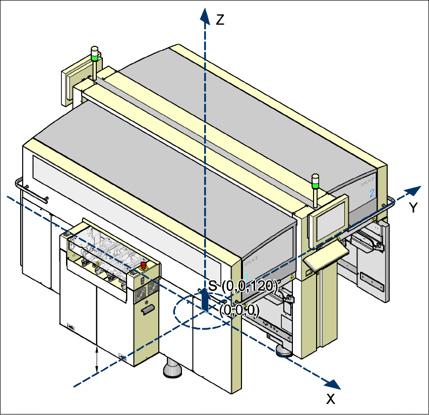
Fig. 3.4 - 9 Center of gravity of the X-series machines in millimeters
3
X coordinate 0 mm
Y coordinate 0 mm
Z coordinate 120 mm high
These center of gravity coordinates relate to placement systems with a PCB transport height of
830 mm.
User manual SIPLACE X-Series 3 Technical data
Software Version SR.601.xx 11/2005 US Edition 3.4 Dimensions and weight of the placement machine
111
3.4.11 Dimensions of the X3 placement system with matrix tray changer
3
3
3
3
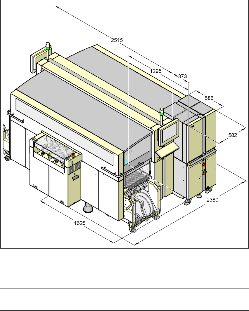
Fig. 3.4 - 10 Dimensions of the X3 placement system with matrix tray changer in millimeters
3
PLEASE NOTE 3
The matrix tray changer can only be docked in at location 2.