X3_X4_Series machine - 第119页
User manual SIPLAC E X-Series 3 Technical data Software Vers ion SR.601.xx 11/ 2005 US Ed ition 3.7 Placem ent heads 119 3.7.1.3 Placement head configura t ion on the X2 placement machine 3 Fig. 3.7 - 3 Head modularity -…
3 Technical data User manual SIPLACE X-Series
3.7 Placement heads Software Version SR.601.xx 11/2005 US Edition
118
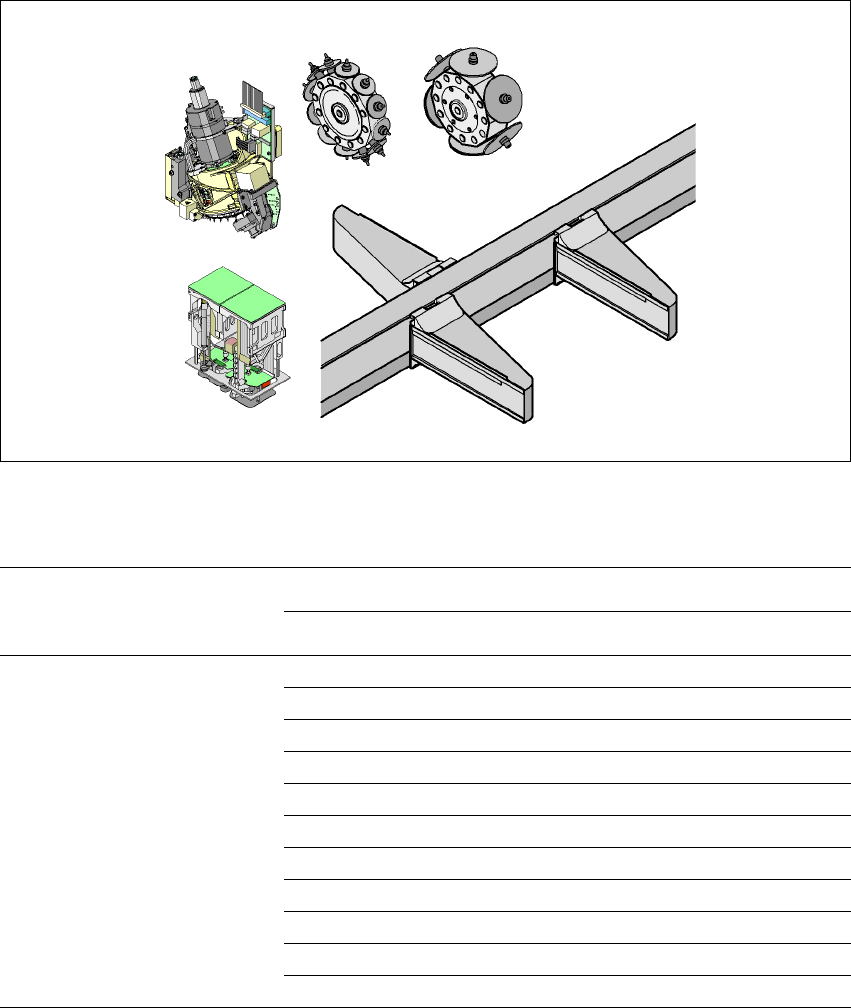
3.7.1.2 Placement head configuration on the X3 placement machine
3
3
Fig. 3.7 - 2 Head modularity - SIPLACE X3
Placement area 2
Placement area 1
TH
C&P12
G1
G3
G4
C&P20/C&P12/C&P6/TH
C&P20/C&P12/C&P6
C&P20/C&P12/C&P6
C&P6
C&P20
Placement area 1 Placement area 2
Gantry 1 Gantry 4 Gantry 3
Placement head C&P20 C&P20 C&P20
C&P20 C&P20 C&P12
C&P20 C&P20 C&P6
C&P20 C&P20 TH
C&P12 C&P12 C&P12
C&P12 C&P12 C&P6
C&P12 C&P12 TH
C&P12 C&P6 C&P6
C&P12 C&P6 TH
C&P6 C&P6 C&P6
C&P6 C&P6 TH
User manual SIPLACE X-Series 3 Technical data
Software Version SR.601.xx 11/2005 US Edition 3.7 Placement heads
119
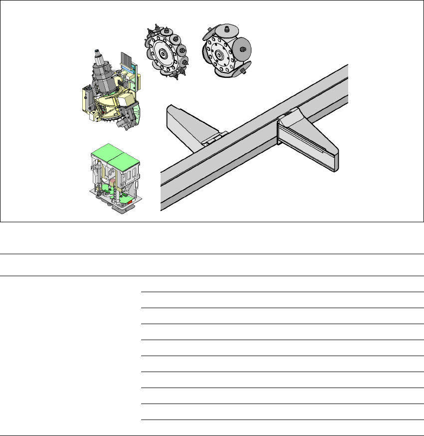
3.7.1.3 Placement head configuration on the X2 placement machine
3
Fig. 3.7 - 3 Head modularity - SIPLACE X2
When you order a SIPLACE X-series placement system, you can select the ideal head configura-
tion for your needs. The placement machine will be configured and supplied as per your order.
There is also a reconfiguration kit if you wish to change the placement head locally. This package
contains the necessary assembly parts, cables, etc., in addition to the placement head. Before
changing the placement head, you should first adapt the station and SIPLACE Pro software. The
system will then have to be recalibrated.
Head modularity, i.e. adapting the placement machine to the production requirements by chang-
ing the placement head, has the advantage that it is an easy way to match the placement machine
to your production needs without having to invest in further machines.
Placement area 2
Placement area 1
TH
C&P12
G1
G3
C&P20/C&P12/C&P6/TH
C&P20/C&P12/C&P6/TH
C&P6
C&P20
Placement area 1, gantry 1 Placement area 2, gantry 3
Placement head C&P20 C&P20
C&P20 C&P12
C&P20 C&P6
C&P20 TH
C&P12 C&P12
C&P12 C&P6
C&P12 TH
C&P6 C&P6
C&P6 TH
TH TH
3 Technical data User manual SIPLACE X-Series
3.7 Placement heads Software Version SR.601.xx 11/2005 US Edition
120
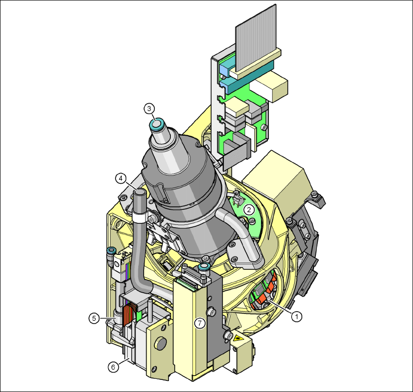
3.7.2 20-nozzle Collect&Place head for very high-speed placement
3
Fig. 3.7 - 4 20-segment Collect&Place head - Function groups, part 1
(1) DP drive, 20 drives
(2) "Vacuum sensor holding circuit" board
(3) Compressed air connection for 20 Venturi nozzles in the pick-up/placement and holding
circuit
(4) Line for the exhaust air from the pressure control valve (7)
(5) Return cylinder
(6) Z motor (linear motor)
(7) Pressure control valve