X3_X4_Series machine - 第130页
3 Technical data User manual SIPLACE X-Series 3.7 Placement heads Software Version SR.601.xx 11/2005 US Edition 130 then set do wn gentl y and ac curately o n the PC B with a b last of ai r . The twel ve nozzle s on SIPL…
User manual SIPLACE X-Series 3 Technical data
Software Version SR.601.xx 11/2005 US Edition 3.7 Placement heads
129
3
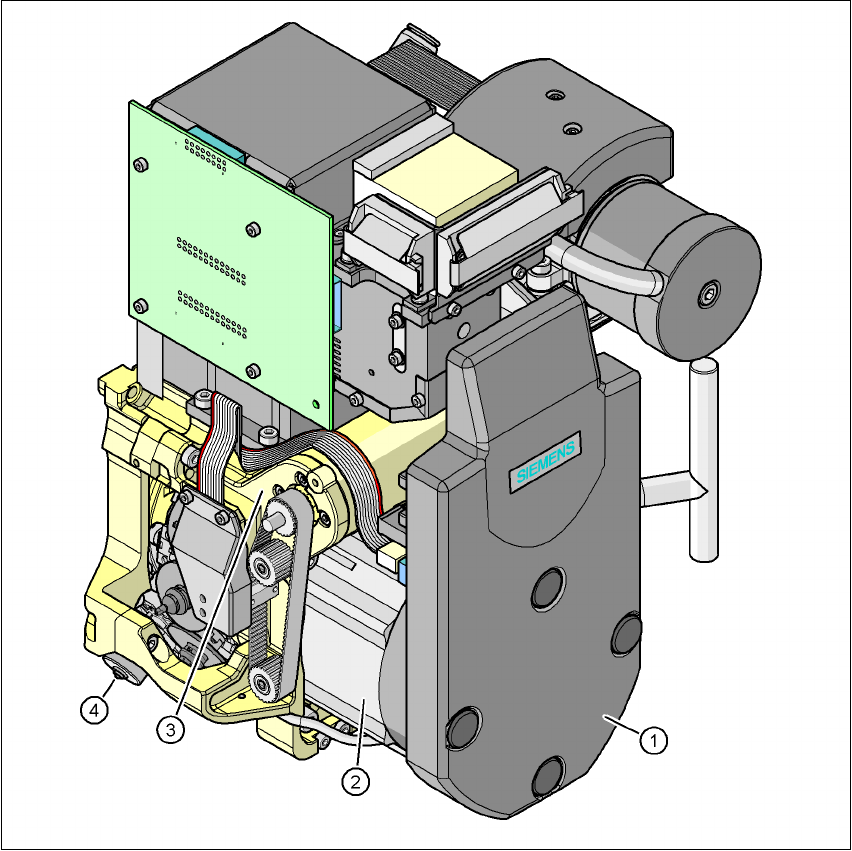
Fig. 3.7 - 8 12-segment Collect&Place head - Function groups, part 2
3
(1) Intermediate distributor board (beneath the cover)
(2) Star drive - DR motor
(3) Z axis motor
(4) Valve adjustment drive
(5) C&P component camera, type 28 (18 x 18) digital or type 29 (27 x 27) digital, high resolution
3.7.3.1 Description
The 12-segment Collect&Place head works on the Collect&Place principle. This means that,
within each cycle, twelve components are picked up by the placement head, are optically centered
on the way to the placement position and are rotated into the required placement angle. They are

3 Technical data User manual SIPLACE X-Series
3.7 Placement heads Software Version SR.601.xx 11/2005 US Edition
130
then set down gently and accurately on the PCB with a blast of air. The twelve nozzles on
SIPLACE Collect&Place heads turn about a horizontal axis, in contrast to conventional chip
shooters. This does not simply save space: the small diameter means that substantially smaller
centrifugal forces occur in comparison to conventional chip shooters. This largely eliminates the
risk of components slipping during transportation.
And there is yet another benefit: the cycle time of the Collect&Place head is the same for all com-
ponents, which means that the placement rate is not dependent on the component size.
3.7.3.2 Checking and self-learning functions
The reliability of the 12-segment Collect&Place head is increased by checking and self-learning
functions.
– The vertical axis (Z axis) for picking up and placing the component works in sensor stop
mode, in which differences in height during pick-up and any unevenness of the PCB surface
are compensated during placement. The average of the deviations during the last 10 place-
ment operations is also taken into account when adapting the further stroke and placement
speeds. The programmed placement force always remains constant.
– Vacuum checks at the nozzles indicate whether the component was picked up or set down
correctly.
– A component sensor may be installed on the C&P head in order to increase placement reli-
ability. The component sensor checks the edge ratio of the components, in addition to
whether the component is present at the nozzle. In this way it is possible to determine
whether the component was picked up by the nozzle transversely or on edge.
– The package form is also checked, and the component is not placed if the geometric data
thus determined differs from the programmed data.
– A digital component camera on the placement head determines the precise position of each
component at the nozzle. The standard camera can be used to optically center size 0.5 x
0.5 mm² to 18.7 x 18.7 mm² components. Any deviations from the required pick-up position
are corrected before placement takes place. When a component is picked up, the average of
the deviations for the last 10 placement operations is taken into account. This further in-
creases the pick-up accuracy.
– The optional high-resolution component camera allows the 12-segment Collect & Place head
to optically center and place component sizes ranging from 0.3 x 0.3 mm² to 18.7 x 18.7 mm².
The high-resolution digital component camera optimizes the speed and accuracy when plac-
ing high-speed flip-chips and bare die components. The values are shown in the table on
page 132
.
3.7.3.3 Description of the functions
The 12-segment Collect&Place head has three axes - the DR or star axis, the Z axis and the
DP axis.
User manual SIPLACE X-Series 3 Technical data
Software Version SR.601.xx 11/2005 US Edition 3.7 Placement heads
131
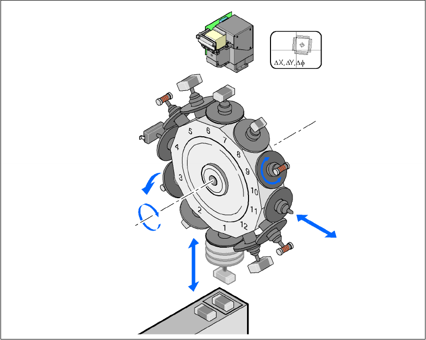
The star rotates about the
star axis
with its 12 segments. The segments hold the sleeves. There
is a nozzle seated on every sleeve, which sucks up the components, and transports them from
the pick-up/placement position (1) to the reject position (3), to the optical centering position (7) or
to the turning position (9).
The
Z axis
performs a vertical movement. Every sleeve that is in the bottom star position (1) is
raised or lowered by this axis, thus picking up the components from the feeder modules and set-
ting them down on the PCB. The Z axis is an "intelligent axis". It "notes" the pick-up height of each
feeder module track and the placement height for each component. This can speed up the place-
ment process. The programmed placement force remains constant.
3
Fig. 3.7 - 9 Description of the functions
The
DP axis
rotates the optically centered component to the desired placement angle. The se-
quences of movements of the rotation and translation axes are controlled by control circuits. Po-
sition and speed sensors send the actual values for the axis movement to the axis control. The
setpoint and actual values are compared and used to determine the force and speed parameters
for the servo amplifier, and thus the axis movement to be performed. The vacuum values at the
nozzle are constantly checked throughout the entire pick-up and placement process in order to
keep the placement error rate as low as possible.
Component camera
DP axis
Rotate component
into placement position
Remove sleeve
or insert
Z axis
Pick up component
or place it
Star axis
Star rotation
Reject component