X3_X4_Series machine - 第132页
3 Technical data User manual SIPLACE X-Series 3.7 Placement heads Software Version SR.601.xx 11/2005 US Edition 132 3.7.3.4 T echnical dat a 3 *) Please note that the component range that can be placed is also affected b…
User manual SIPLACE X-Series 3 Technical data
Software Version SR.601.xx 11/2005 US Edition 3.7 Placement heads
131
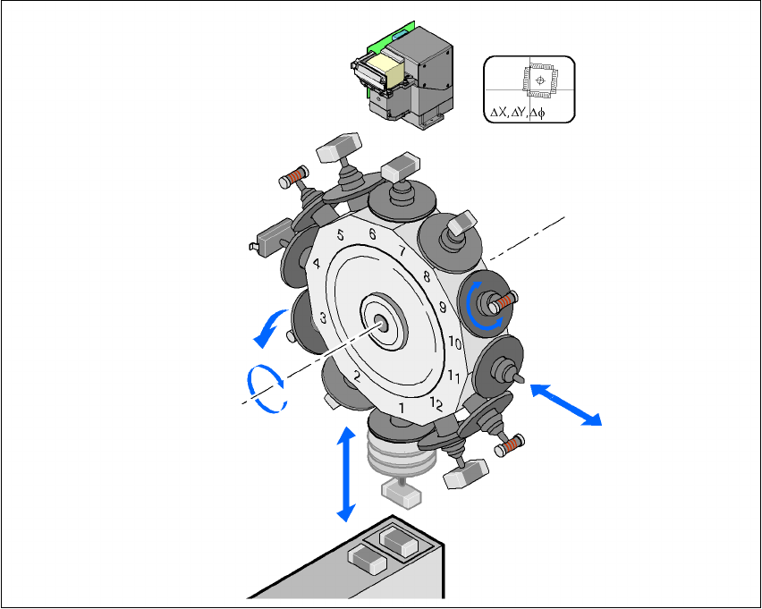
The star rotates about the
star axis
with its 12 segments. The segments hold the sleeves. There
is a nozzle seated on every sleeve, which sucks up the components, and transports them from
the pick-up/placement position (1) to the reject position (3), to the optical centering position (7) or
to the turning position (9).
The
Z axis
performs a vertical movement. Every sleeve that is in the bottom star position (1) is
raised or lowered by this axis, thus picking up the components from the feeder modules and set-
ting them down on the PCB. The Z axis is an "intelligent axis". It "notes" the pick-up height of each
feeder module track and the placement height for each component. This can speed up the place-
ment process. The programmed placement force remains constant.
3
Fig. 3.7 - 9 Description of the functions
The
DP axis
rotates the optically centered component to the desired placement angle. The se-
quences of movements of the rotation and translation axes are controlled by control circuits. Po-
sition and speed sensors send the actual values for the axis movement to the axis control. The
setpoint and actual values are compared and used to determine the force and speed parameters
for the servo amplifier, and thus the axis movement to be performed. The vacuum values at the
nozzle are constantly checked throughout the entire pick-up and placement process in order to
keep the placement error rate as low as possible.
Component camera
DP axis
Rotate component
into placement position
Remove sleeve
or insert
Z axis
Pick up component
or place it
Star axis
Star rotation
Reject component
3 Technical data User manual SIPLACE X-Series
3.7 Placement heads Software Version SR.601.xx 11/2005 US Edition
132
3.7.3.4 Technical data
3
*) Please note that the component range that can be placed is also affected by the pad geometry, the customer-specific
standards and the packaging tolerances.
12-segment Collect&Place head
with standard component
camera type 28, 18 x 18, digital
12-segment Collect&Place head
with high-resolution component
camera, type 29, 27 x 27, digital
Component range *) 0402 to PLCC44, BGA, µBGA,
flip-chip, TSOP, QFP, SO to
SO32, DRAM
0201 to flip-chip, bare die,
PLCC44, BGA, µBGA, TSOP,
QFP, SO to SO32, DRAM
Component specification
Max. height
Min. lead pitch
Min. ball pitch
Min. ball diameter
Min. dimensions
Max. dimensions
Max. weight
6 mm
0.5 mm
0.45 mm
0.25 mm
0.5 x 0.5 mm²
18.7 x 18.7 mm²
2 g
6 mm
0.3 mm
0.25 mm
0.14 mm
0.3 x 0.3 mm²
18.7 x 18.7 mm²
2 g
Programmed power stage
1
2
3
4
5
Programmed set-down force [N]
2.4 ± 0.5
2.4 ± 0.5
3 + 1
4 + 1
5 + 1
Nozzle types 9 xx 9 xx
X/Y accuracy ± 45 µm/3 σ, ± 60 µm/4 σ ± 41 µm/3 σ, ± 55 µm/4 σ
Angular accuracy ± 0.5°/3 σ, ± 0.7°/4 σ ± 0.5°/3 σ, ± 0.7°/4 σ
User manual SIPLACE X-Series 3 Technical data
Software Version SR.601.xx 11/2005 US Edition 3.7 Placement heads
133
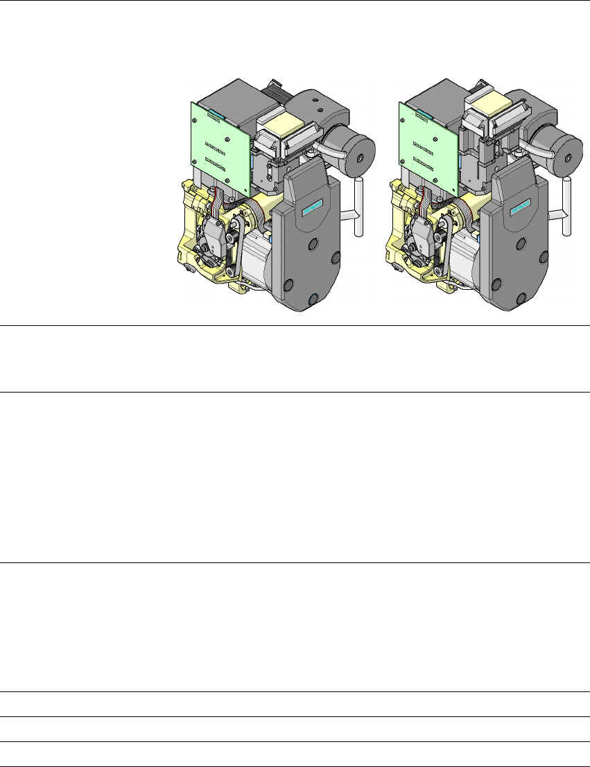
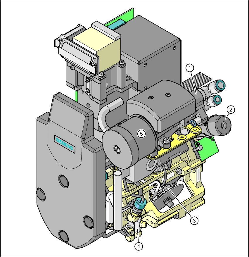
3.7.4 6-segment Collect&Place head for high-speed IC placement
3
Fig. 3.7 - 10 6-segment Collect&Place head - Function groups, part 1
3
(1) Vacuum generator
(2) Turning station, DP axis
(3) Star with 6 sleeves - star axis
(4) Forced air valve
(5) Silencer