X3_X4_Series machine - 第134页
3 Technical data User manual SIPLACE X-Series 3.7 Placement heads Software Version SR.601.xx 11/2005 US Edition 134 3 Fig. 3.7 - 1 1 6-segment Collect&Place head - Function groups, part 2 3 (1) Int ermediate di strib…
User manual SIPLACE X-Series 3 Technical data
Software Version SR.601.xx 11/2005 US Edition 3.7 Placement heads
133
3.7.4 6-segment Collect&Place head for high-speed IC placement
3
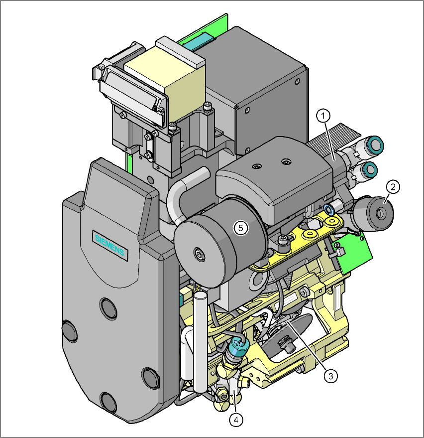
Fig. 3.7 - 10 6-segment Collect&Place head - Function groups, part 1
3
(1) Vacuum generator
(2) Turning station, DP axis
(3) Star with 6 sleeves - star axis
(4) Forced air valve
(5) Silencer
3 Technical data User manual SIPLACE X-Series
3.7 Placement heads Software Version SR.601.xx 11/2005 US Edition
134
3
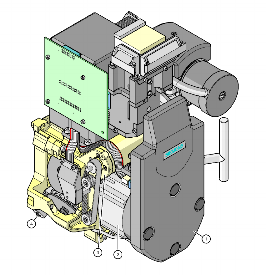
Fig. 3.7 - 11 6-segment Collect&Place head - Function groups, part 2
3
(1) Intermediate distributor board, beneath the cover
(2) Star drive - DR motor
(3) Z axis motor
(4) Valve adjustment drive
(5) C&P component camera, type 29, 27 x 27, digital
User manual SIPLACE X-Series 3 Technical data
Software Version SR.601.xx 11/2005 US Edition 3.7 Placement heads
135
3.7.4.1 Description
The 6-segment Collect&Place head also works on the Collect&Place principle. The high-resolu-
tion digital component camera allows the 6-segment Collect&Place head to place components
with an edge length of up to 27 mm accurately and very quickly. It is therefore ideal for use with
products containing a large proportion of ICs. A considerable increase in output can be achieved
even in the main application range from PLCC 44 to QFP 208.
3.7.4.2 Checking and self-learning functions
The checking and self-learning functions described on page 130 for the 12-segment
Collect&Place head also apply to the 6-segment Collect&Place head.
3.7.4.3 Description of the functions
3
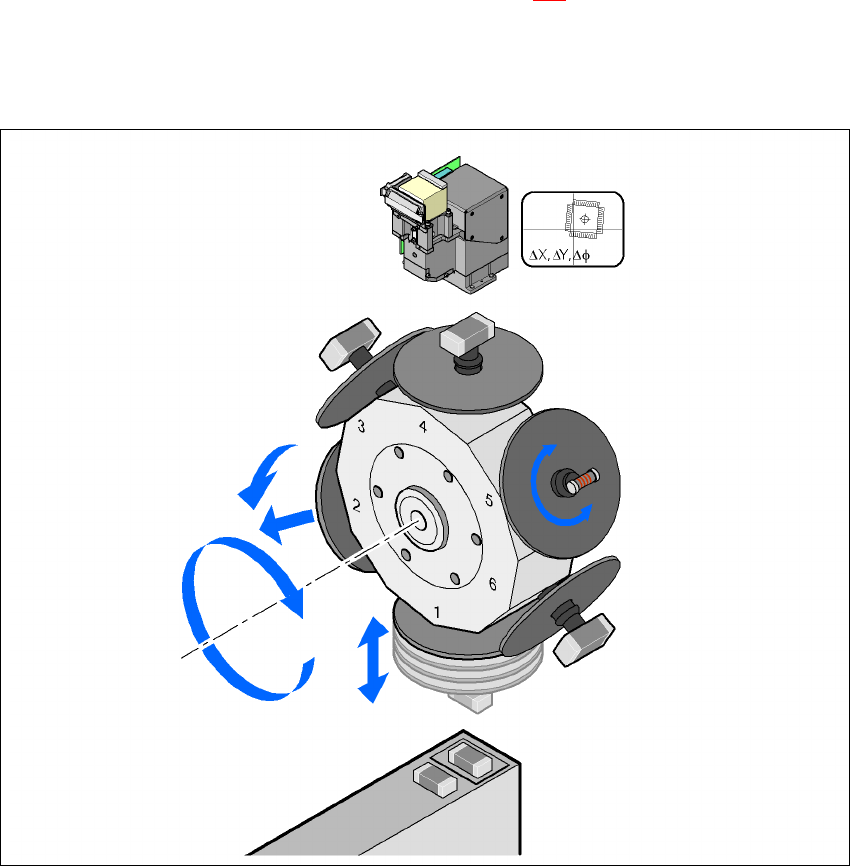
Fig. 3.7 - 12 Description of the functions
Component camera
DP axis
Rotate component
into placement position
Remove sleeve
or insert
Z axis
Pick up component
or place it
Star axis
Star rotation
Reject component