X3_X4_Series machine - 第149页
User manual SIPLAC E X-Series 3 Technical data Software Version SR.601.xx 11/2005 US Edition 3.10 Gantries 149 3.10.2 Posit ion of the gantri es for the X3 pla cement machine 3 Fig. 3.10 - 2 Position of the gantries for …
3 Technical data User manual SIPLACE X-Series
3.10 Gantries Software Version SR.601.xx 11/2005 US Edition
148
3.10 Gantries
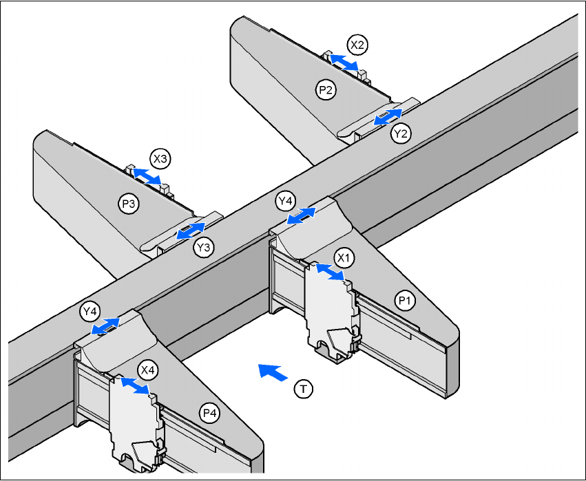
3.10.1 Position of the gantries for the X4 placement machine
3
Fig. 3.10 - 1 Position of the gantries for the X4 placement machine
G1, G2, G3, G4 (gantry 1, gantry 2, gantry 3, gantry 4)
X1 X axis, gantry 1
Y1 Y axis, gantry 1
X2 X axis, gantry 2
Y2 Y axis, gantry 2
X3 X axis, gantry 3
Y3 Y axis, gantry 3
X4 X axis, gantry 4
Y4 Y axis, gantry 4
(T) Direction of PCB transport
Placement area 2
Placement area 1
User manual SIPLACE X-Series 3 Technical data
Software Version SR.601.xx 11/2005 US Edition 3.10 Gantries
149
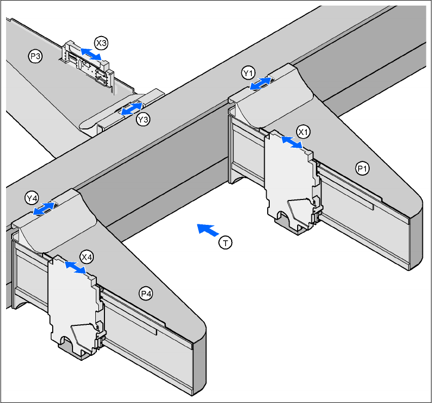
3.10.2 Position of the gantries for the X3 placement machine
3
Fig. 3.10 - 2 Position of the gantries for the X3 placement machine
G1 Gantry 1
X1 X axis, gantry 1
Y1 Y axis, gantry 1
P3 Gantry 3
X3 X axis, gantry 3
Y3 Y axis, gantry 3
P4 Gantry 4
X4 X axis, gantry 4
Y4 Y axis, gantry 4
(T) Direction of PCB transport
Placement area 2
Placement area 1
3 Technical data User manual SIPLACE X-Series
3.10 Gantries Software Version SR.601.xx 11/2005 US Edition
150
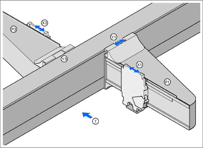
3.10.3 Position of the gantries for the X2 placement machine
3
Fig. 3.10 - 3 Position of the gantries for the X2 placement machine
G1 Gantry 1
X1 X axis, gantry 1
Y1 Y axis, gantry 1
P3 Gantry 3
X3 X axis, gantry 3
Y3 Y axis, gantry 3
(T) Direction of PCB transport
The gantry system consists of two functional groups
–X axis and
–Y axis
Placement area 2
Placement area 1