X3_X4_Series machine - 第16页
Contents User manual SIPLAC E X-Series 11/2005 US Edition 16
User manual SIPLACE X-Series Contents
11/2005 US Edition
15
7.5 PCB barcode scanner . . . . . . . . . . . . . . . . . . . . . . . . . . . . . . . . . . . . . . . . . . . . . . . . . . . . . . . . . 417
7.5.1 Overview . . . . . . . . . . . . . . . . . . . . . . . . . . . . . . . . . . . . . . . . . . . . . . . . . . . . . . . . 417
7.5.2 Description of the functions . . . . . . . . . . . . . . . . . . . . . . . . . . . . . . . . . . . . . . . . . . 418
7.5.3 Technical data – 1D barcode scanner. . . . . . . . . . . . . . . . . . . . . . . . . . . . . . . . . . 419
7.5.4 Technical data – 2D barcode scanner. . . . . . . . . . . . . . . . . . . . . . . . . . . . . . . . . . 419
7.5.5 Warning label W216 on the cover of the PCB input side . . . . . . . . . . . . . . . . . . . 420
7.5.6 Assembly options for the PCB barcode scanner. . . . . . . . . . . . . . . . . . . . . . . . . . 421
7.5.7 Positioning PCB barcode labels on the PCB. . . . . . . . . . . . . . . . . . . . . . . . . . . . . 422
7.5.7.1 Positioning along the long side of the PCB -
Scanning beam across the direction of travel . . . . . . . . . . . . . . . . . . . . . . . . . . . . 422
7.5.7.2 Positioning along the long side of the PCB -
Scanning beam along the direction of travel . . . . . . . . . . . . . . . . . . . . . . . . . . . . . 422
7.5.7.3 PCB overshoot over the machine with the dual conveyor. . . . . . . . . . . . . . . . . . . 423
7.5.7.4 Positioning along the width of the PCB -
Scanning beam across the direction of travel . . . . . . . . . . . . . . . . . . . . . . . . . . . . 423
7.5.7.5 Positioning along the width of the PCB -
Scanning beam along the direction of travel,
PCB barcode scanner 1D topside. . . . . . . . . . . . . . . . . . . . . . . . . . . . . . . . . . . . . 424
7.5.7.6 Positioning along the width of the PCB -
Scanning beam along the direction of travel,
PCB barcode scanner 1D underside. . . . . . . . . . . . . . . . . . . . . . . . . . . . . . . . . . . 424
7.6 PCB alignment . . . . . . . . . . . . . . . . . . . . . . . . . . . . . . . . . . . . . . . . . . . . . . . . . . . . . . . . . . . . . . . 425
7.6.1 General . . . . . . . . . . . . . . . . . . . . . . . . . . . . . . . . . . . . . . . . . . . . . . . . . . . . . . . . . 425
7.6.2 Description of the functions . . . . . . . . . . . . . . . . . . . . . . . . . . . . . . . . . . . . . . . . . . 426
7.7 SIEMENS interface. . . . . . . . . . . . . . . . . . . . . . . . . . . . . . . . . . . . . . . . . . . . . . . . . . . . . . . . . . . . 426
7.8 Long board option . . . . . . . . . . . . . . . . . . . . . . . . . . . . . . . . . . . . . . . . . . . . . . . . . . . . . . . . . . . . 427
7.9 Magnetic pin support . . . . . . . . . . . . . . . . . . . . . . . . . . . . . . . . . . . . . . . . . . . . . . . . . . . . . . . . . 428
7.10 Feeder module cover flap (S feeder module) . . . . . . . . . . . . . . . . . . . . . . . . . . . . . . . . . . . . . . 429
7.11 Component sensor for the C&P12 head . . . . . . . . . . . . . . . . . . . . . . . . . . . . . . . . . . . . . . . . . . 430
7.11.1 Description of the functions of the component sensor . . . . . . . . . . . . . . . . . . . . . 431
7.11.2 Measuring conditions . . . . . . . . . . . . . . . . . . . . . . . . . . . . . . . . . . . . . . . . . . . . . . 431
7.12 Coplanarity laser module . . . . . . . . . . . . . . . . . . . . . . . . . . . . . . . . . . . . . . . . . . . . . . . . . . . . . . 433
7.12.1 Description of the functions . . . . . . . . . . . . . . . . . . . . . . . . . . . . . . . . . . . . . . . . . . 433
7.12.2 Technical data . . . . . . . . . . . . . . . . . . . . . . . . . . . . . . . . . . . . . . . . . . . . . . . . . . . . 434
7.12.3 Safety instructions . . . . . . . . . . . . . . . . . . . . . . . . . . . . . . . . . . . . . . . . . . . . . . . . . 435
7.12.4 Warning label W216 on the cover beside the main switch . . . . . . . . . . . . . . . . . . 436
7.12.5 LED displays on the controller. . . . . . . . . . . . . . . . . . . . . . . . . . . . . . . . . . . . . . . . 437
7.13 Vacuum pump . . . . . . . . . . . . . . . . . . . . . . . . . . . . . . . . . . . . . . . . . . . . . . . . . . . . . . . . . . . . . . . 439
7.14 SIPLACE productivity lift . . . . . . . . . . . . . . . . . . . . . . . . . . . . . . . . . . . . . . . . . . . . . . . . . . . . . . 440
7.14.1 Concept of parallel placement. . . . . . . . . . . . . . . . . . . . . . . . . . . . . . . . . . . . . . . . 440
7.14.2 Implementing parallel placement. . . . . . . . . . . . . . . . . . . . . . . . . . . . . . . . . . . . . . 441
7.14.3 Advantages of the productivity lift . . . . . . . . . . . . . . . . . . . . . . . . . . . . . . . . . . . . . 442
Contents User manual SIPLACE X-Series
11/2005 US Edition
16
User manual SIPLACE X-Series 1 Introduction
Software Version SR.601.xx 11/2005 US Edition
17
1 Introduction
These operating instructions provide a manual or reference work for operating and setting up the
placement machines for the X-series.
1
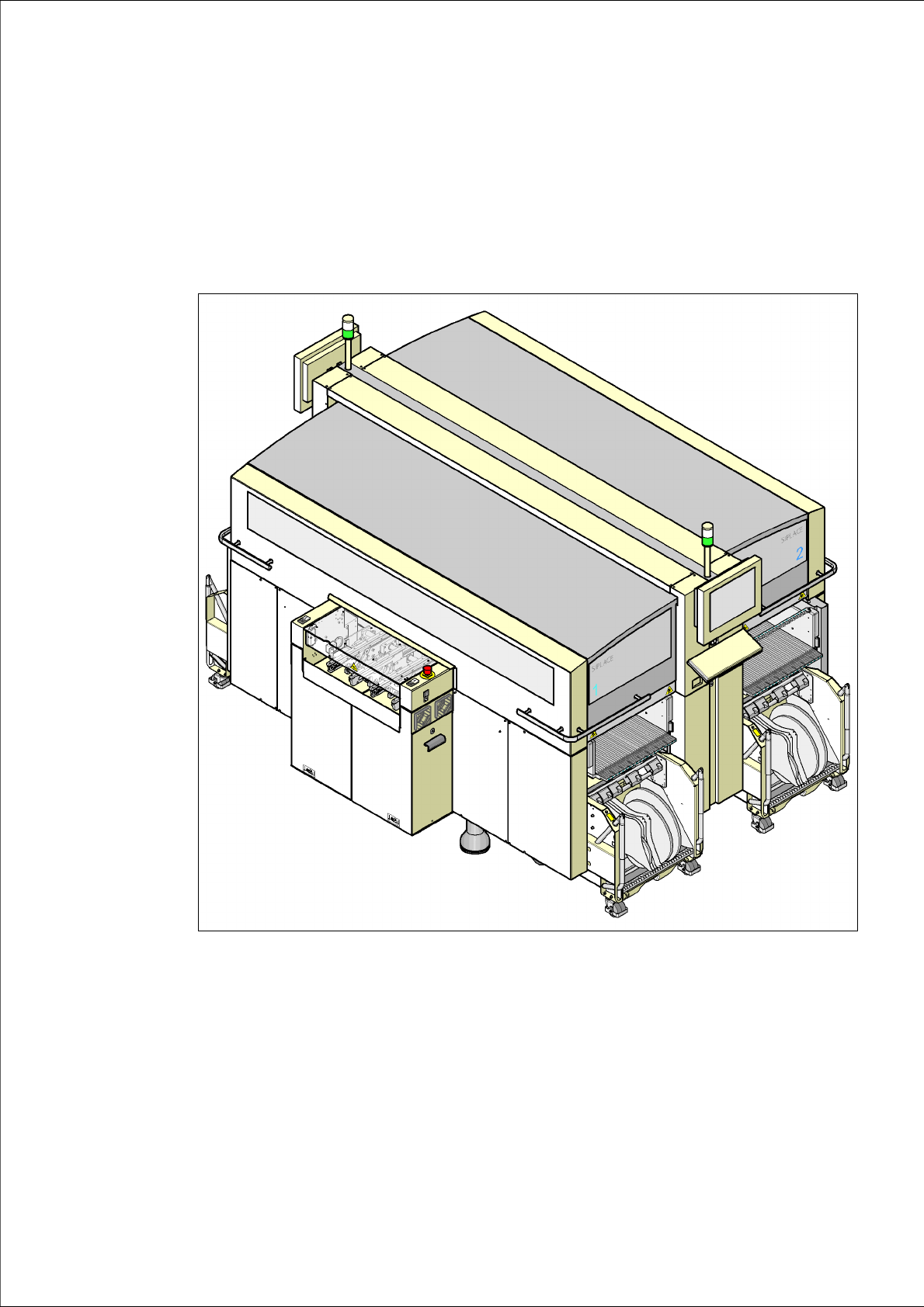
Fig. 1.0 - 1 SIPLACE X4 placement machine
The header of each chapter contains the
– release and
– software version
to which this manual applies. 1