X3_X4_Series machine - 第160页
3 Technical data User manual SIPLACE X-Series 3.11 Vision cameras Software Version SR.601.xx 11/2005 US E dition 160 3.1 1.4 St ationary P &P compone nt camera , type 33, 55 x 45 , digit al 3.1 1.4.1 Structu re 3 Fig…
User manual SIPLACE X-Series 3 Technical data
Software Version SR.601.xx 11/2005 US Edition 3.11 Vision cameras
159
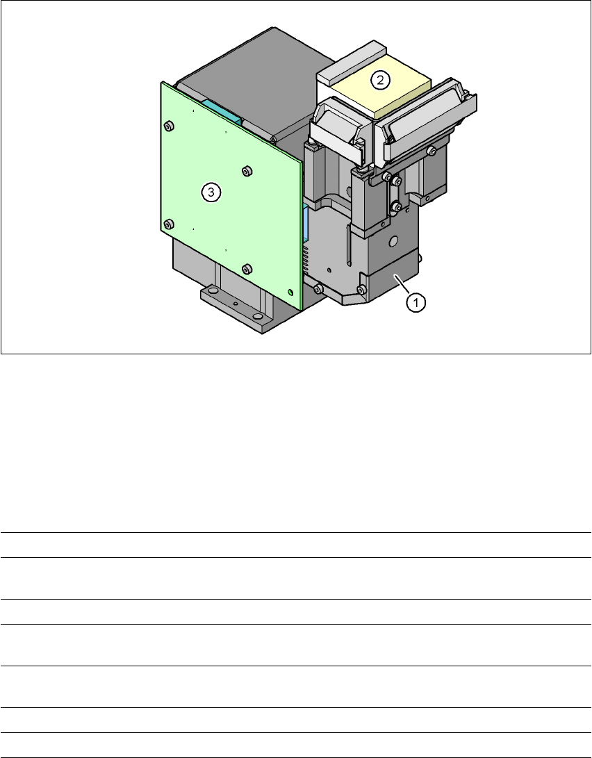
3.11.3 C&P component camera, type 29, 27 x 27, digital
3.11.3.1 Structure
3
Fig. 3.11 - 4 C&P component camera, type 29, 27 x 27, digital
(1) Component camera lens and illumination
(2) Camera amplifier
(3) Illumination control
3.11.3.2 Technical data
3
Component dimensions 0.3 x 0.3 mm² to 27 x 27 mm²
Range of components 0201 to 27 x 27 mm²
PLCC, SO, QFP, TSDP, SOT, MELF, CHIP, IC BGA
Min. lead pitch 0.3 mm
Min. ball pitch 0.25 mm for components < 18 x 18 mm²
0.35 mm for components ≥ 18 x 18 mm²
Min. ball diameter 0.14 mm for components < 18 x 18 mm²
0.2 mm for components ≥ 18 x 18 mm²
Field of vision 31 x 31 mm²
Method of illumination Front-lighting (5 levels, programable as required)
3 Technical data User manual SIPLACE X-Series
3.11 Vision cameras Software Version SR.601.xx 11/2005 US Edition
160
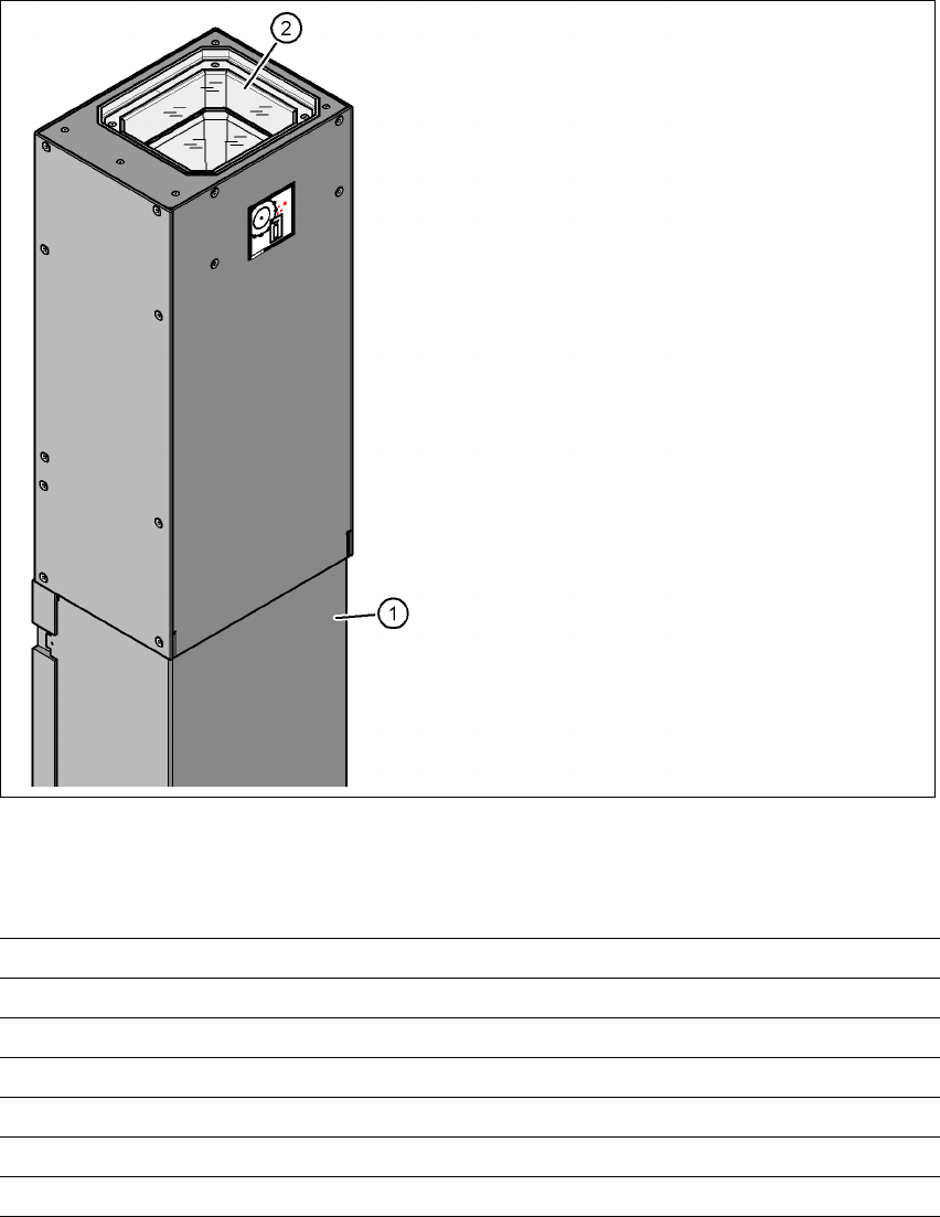
3.11.4 Stationary P&P component camera, type 33, 55 x 45, digital
3.11.4.1 Structure
3
Fig. 3.11 - 5 Structure for the stationary P&P component camera, type 33, 55 x 45, digital
3.11.4.2 Technical data
3
(1) Camera housing with integral camera
and camera amplifier
(2) Glass plate - over the illumination and
lens levels
Component dimensions 0.5 x 0.5 mm² to 55 x 45 mm²
Range of components 0402, MELF, SO, PLCC, QFP, electrolytic capacitors, BGA
Min. lead pitch 0.3 mm
Min. ball pitch 0.45 mm
Min. ball diameter 0.25 mm
Field of vision 65 x 50 mm²
Method of illumination Front-lighting (6 levels, programable as required)
User manual SIPLACE X-Series 3 Technical data
Software Version SR.601.xx 11/2005 US Edition 3.11 Vision cameras
161
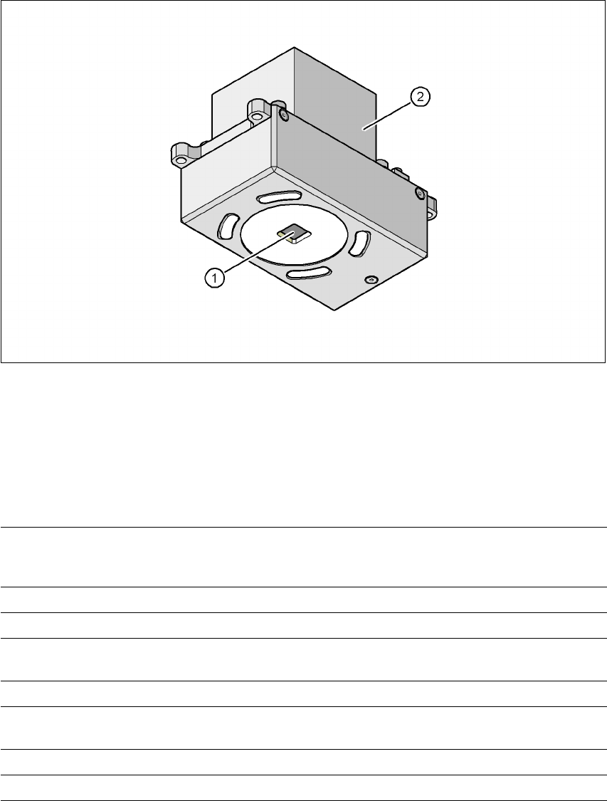
3.11.5 PCB camera, type 34, digital
3.11.5.1 Structure
3
Fig. 3.11 - 6 Digital PCB camera, type 34
(1) PCB camera lens and illumination
(2) Camera amplifier
3
3.11.5.2 Technical data
3
PCB fiducials Up to 3 (subpanels and multiple panels)
Up to 6 for the Long board option (Optional PCB fiducials are
output by the optimization.)
Local fiducials Up to 2 per PCB (may be of different type)
Library memory Up to 255 fiducial types per subpanel
Image analysis Edge detection method (Singular feature) based on grayscale
values
Lighting method Front-lighting (3 levels, programable as required)
Detection time per
fiducial/bad fiducial
20 ms - 200 ms
Field of vision 5.7 x 5.7 mm²
Distance from the focus plane 28 mm