X3_X4_Series machine - 第168页
3 Technical data User manual SIPLACE X-Series 3.13 Flexible dual PCB conveyor Software Version S R.601.xx 11/2005 US Edition 168 3.13.3 Description of the functions The flexib le dua l convey or has two conve yor track s…

User manual SIPLACE X-Series 3 Technical data
Software Version SR.601.xx 11/2005 US Edition 3.13 Flexible dual PCB conveyor
167
3.13.2 Technical data
3
Fixed conveyor side Right or left
PCB format
Standard (length x width)
"Wide board" configuration
Long board option
Long board option in "Wide board"
configuration
Dual conveyor in "Single conveyor"
mode
Standard (length x width)
"Wide board" configuration
Long board option
Long board option in "Wide board"
configuration
50 x 50 mm² to 450 x 216 mm² (item no. 00119627-xx)
50 x 50 mm² to 450 x 250 mm² (item no. 00119629-xx)
50 x 80 mm² to 610 x 216 mm² (item no. 00119672-xx)
50 x 80 mm² to 610 x 250 mm²
50 x 50 mm² to 450 x 380 mm²
50 x 50 mm² to 450 x 450 mm²
50 x 80 mm² to 610 x 380 mm²
50 x 80 mm² to 610 x 450 mm²
PCB thickness
Standard 0.3 mm to 4.5 mm ± 0.2 mm
(thicker PCBs available on request)
Max. PCB warpage Up: 6 mm - PCB thickness
Down: 0.3 mm + PCB thickness
PCB weight Max. 3 kg
Clearance on PCB underside
Standard
Option
25 mm ± 0.2 mm
Max. 40 mm ± 0.2 mm
PCB transport height 830mm ± 15mm (standard)
900mm ± 15mm (optional)
930mm ± 15mm (optional)
950mm ± 15mm (SMEMA: optional)
Type of interface SMEMA / SIEMENS
Component-free PCB handling edge 3 mm
PCB changeover time < 2.5 s
PCB positioning accuracy ± 0.5 mm
Conveyor mode Synchronous or asynchronous
Components on each conveyor Same or different
PCB width on each conveyor Same or different
Bad fiducial detection Synchronous: impossible, asynchronous: possible
Automatic width adjustment Synchronous: possible, asynchronous: possible
3 Technical data User manual SIPLACE X-Series
3.13 Flexible dual PCB conveyor Software Version SR.601.xx 11/2005 US Edition
168
3.13.3 Description of the functions
The flexible dual conveyor has two conveyor tracks that are electrically and mechanically inde-
pendent of one another. The functions are the same as for the single conveyor (see Section
3.12.3
, page 164.
3.13.4 "Flexible dual conveyor" performance feature
The "flexible dual conveyor" performance feature allows the conveyor track to be widened beyond
the standard width of 216 mm. Over-wide PCBs can then be processed in a machine with a dual
conveyor. The side walls of the second conveyor track are moved fully together, which deactivates
the conveyor track at the same time.
3
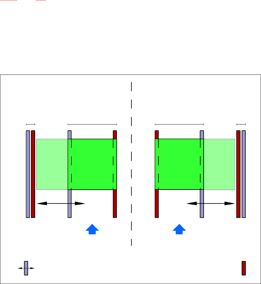
Fig. 3.13 - 2 Flexible dual conveyor in Single conveyor mode
3
3
Dual conveyor with widened conveyor track 2
(stationary conveyor side wall on left)
Conveyor track
2 deactivated
Conveyor track 1 Conveyor track 2 Conveyor track 1
deactivated
PCB transport direction PCB transport direction
Stationary conveyor side wall
Dual conveyor with widened conveyor track 1
(stationary conveyor side wall on right)
Movable conveyor side wall

User manual SIPLACE X-Series 3 Technical data
Software Version SR.601.xx 11/2005 US Edition 3.13 Flexible dual PCB conveyor
169
3.13.5 Defining the conveyor tracks
The right conveyor track (viewed in the transport direction) is designated "Conveyor 1" and the left
as "Conveyor 2" (see Fig. 3.13 - 3
, page 170).
3.13.6 Definition of the conveyor track width
3.13.6.1 Standard width
The standard width of the conveyor track is the maximum conveyor width defined by the desired
position of the stationary conveyor side. It is no more than 216 mm per track.
3.13.6.2 Overwide conveyor track
The conveyor track can be widened to 250 mm maximum by moving the stationary conveyor side
wall out of its normal position.
3.13.6.3 Dual conveyor in Single conveyor mode
The dual conveyor can be configured online to create a single conveyor. To do this, one conveyor
track is moved fully together and deactivated (see Fig. 3.13 - 2
, page 168). This gives a conveyor
track width of up to 450 mm.
3.13.7 Transport modes
The flexible dual conveyor can be used in two modes:
– Synchronous transport mode
– Asynchronous transport mode
3.13.7.1 Asynchronous transport mode
Description 3
In asynchronous mode, only one PCB in a transport track is processed. At the same time, another
PCB in the second transport track is moved into the placement position. This saves the full con-
veying time of one PCB, thus considerably increasing performance, particularly for PCBs with a
short cycle time.
Function 3
Once the machine has received the job data (panel, set-up), the PCBs on the feeding belts are
continuously transported to the available processing belt (provided that the processing belt is free)
throughout the placement operation. The placement sequence starts as soon as a PCB has
moved onto the processing belt. The PCBs are processed one after another.