X3_X4_Series machine - 第182页
4 Setting up and commissioning User manual SIPLACE X-Series 4.3 Infrastructure at t he installation location Software Version SR.601.x x 11/2005 US Edition 182 4.3.1.2 V ibration limit s The placem ent mac hine is not se…

User manual SIPLACE X-Series 4 Setting up and commissioning
Software Version SR.601.xx 11/2005 US Edition 4.3 Infrastructure at the installation location
181
Æ Make sure that the forks are evenly loaded when you lift the machine. A firm support between
the forks and placement machine will prevent the machine tilting when it is raised. This will
also prevent a one-sided load on the machine feet, which would deform the fixing of the ma-
chine feet. We recommend that a second person watch the machine as it is raised, and make
sure that the machine does not tip to one side when lifted with the fork-lift.
4.2.4.4 Points that MUST be noted when transporting the machine
WARNING 4
When you are transporting the machine, make sure that
all
the feet are clear of the floor. If they
are not clear, the feet will drag along the floor or bump into obstacles. This could damage the
machine foot fixing in the machine frame.
4.3 Infrastructure at the installation location
4.3.1 Recommendations concerning the quality of the foundation
The foundation for the placement machine should be firm and flat since dynamic forces can create
vibrations when the placement machine is used. The size of the vibrations depends on the con-
struction of the foundation. The following are suitable provided that the floor loading parameters,
etc., are not exceeded:
– Reinforced concrete ceiling constructions, e.g. ceilings in production halls
– Reinforced concrete floor slabs, e.g. concrete floors in production halls without a basement
– Rooms with double floors, provided that a stable foundation is included in the space between
them. The same set-up conditions apply to this intermediate foundation, which can be made
from steel girders or concrete.
4.3.1.1 Machine weight and floor loading
The machine weight and floor loading values can be found in section 4.1, page 173.
4
4

4 Setting up and commissioning User manual SIPLACE X-Series
4.3 Infrastructure at the installation location Software Version SR.601.xx 11/2005 US Edition
182
4.3.1.2 Vibration limits
The placement machine is not sensitive to ground vibration, but the following vibration limits
should still be observed.
4
4
4
4
4
4.3.2 Compressed air supply
4.3.2.1 Checking the compressed air supply
Check that the compressed air supply conforms to the prescribed machine specifications (see ta-
ble in section 3.3
, page 99).
PLEASE NOTE: 4
The document entitled "Network configuration (electrical and compressed air) for SMD systems
on the customer's premises", item no. 00191409-xx, describes the action that can be taken to
meet the required specifications.
Æ Record the compressed air characteristics at the installation location.
Parameters Values
Third-octave spectral value of the vibration speed 5 - 100 Hz
v < 250 µm/s
v
max
value on the time curve
v
max
< 1.5 mm/s
User manual SIPLACE X-Series 4 Setting up and commissioning
Software Version SR.601.xx 11/2005 US Edition 4.3 Infrastructure at the installation location
183
4.3.2.2 Compressed air connection on the placement machine
4
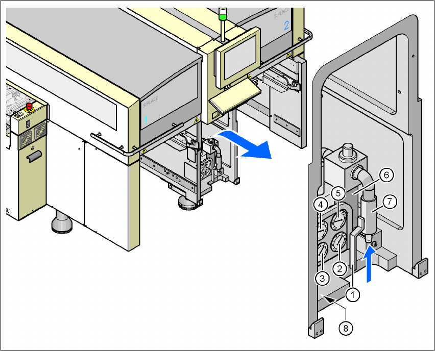
Fig. 4.3 - 1 Compressed air line connection
(1) Stop valve in the "OPEN" position
(2) Manometer for the machine component supply pressure
Desired pressure: 0.5 ± 0.025 MPa, 5 ± 0.25 bar (display range 0 - 0.6 MPa, 0 - 6 bar)
(3) Manometer for the gantry distributor supply pressure
Desired pressure: 0.46 ± 0.01 MPa, 4.6 ± 0.1 bar (display range 0 - 0.6 MPa, 0 - 6 bar)
(4) Manometer for the bulk case feeder modules supply pressure
Desired pressure: 0.25 ± 0.05 MPa, 2.5 ± 0.5 bar (display range 0 - 0.6 MPa, 0 - 6 bar)
(5) Manometer for the input pressure
Desired pressure: 0.5 - 1.0 MPa, 5 - 10 bar (display range: 0 - 1.0 MPa, 0 - 10 bar)
(6) Compressed air filter
(7) Compressed air connection
(8) Hexagon socket head screw for fixing the pneumatic board