X3_X4_Series machine - 第186页
4 Setting up and commissioning User manual SIPLACE X-Series 4.3 Infrastructure at t he installation location Software Version SR.601.x x 11/2005 US Edition 186 W ARNING 4 The electr ical cabl es to eac h indivi dual mac …

User manual SIPLACE X-Series 4 Setting up and commissioning
Software Version SR.601.xx 11/2005 US Edition 4.3 Infrastructure at the installation location
185
4.3.3.1 Danger notes
WARNING
The placement system is supplied with 3 x 208 VAC, 3 x 230 VAC, 3 x 380 VAC, 3 x 400 VAC or
3 x 415 VAC ± 5 %, 50/60 Hz mains voltage. This means that some parts of the system carry po-
tentially lethal voltages - even when switched off at the main power switch. Incorrect handling of
the placement system can therefore result in death or severe injury or considerable damage to
equipment. 4
Æ Always follow the applicable accident prevention and DIN regulations (particularly DIN EN 60
204, part 1).
Æ Only trained and qualified personnel may remove the cover over the power supply unit and
connect the machine to the power supply.
4
4
4.3.3.2 Checking the main power supply
Check that the main power supply conforms to the prescribed machine specifications (see table
in section 3.3
, page 99).
PLEASE NOTE: 4
The document entitled "Network configuration (electrical and compressed air) for SMD systems
on the customer's premises", item no. 00191409-xx, describes the action that can be taken to
meet the required specifications.
4
4
4
4.3.3.3 Power supply cable - specification
The following specifications apply to the power supply cable:
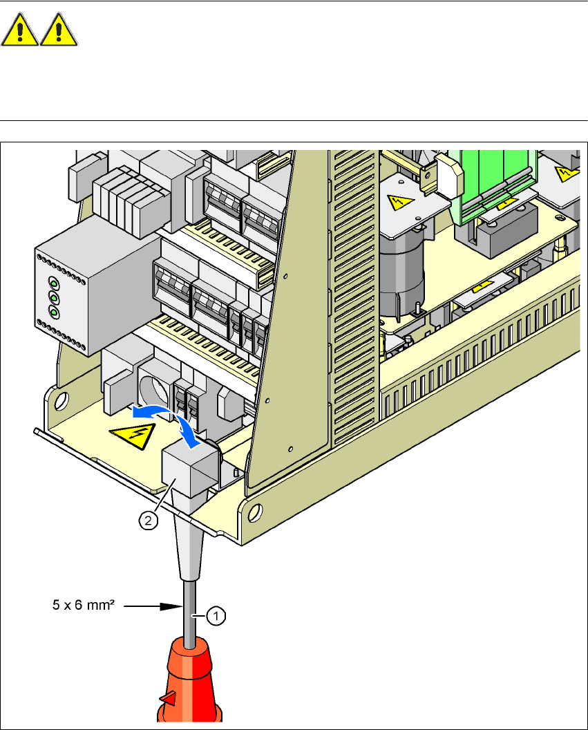
5 x 6 mm² for 3 x 380 VAC / 3 x 400 VAC / 3 x 415 VAC
5 x 6 mm² for 3 x 208 VAC / 3 x 230 VAC
The color coding for the wires will depend on the country in which the system is operated.
4 Setting up and commissioning User manual SIPLACE X-Series
4.3 Infrastructure at the installation location Software Version SR.601.xx 11/2005 US Edition
186
WARNING 4
The electrical cables to each individual machine and to the installed options (e.g. MTC, produc-
tivity lift, vacuum pump) must be clearly identified and there must be no doubt as to their alloca-
tion. The regulations of the country in which the machine is operated apply.
4
Fig. 4.3 - 3 Cross-section of the main power cable
(1) Power supply cable
(2) Angle for the cable gland
User manual SIPLACE X-Series 4 Setting up and commissioning
Software Version SR.601.xx 11/2005 US Edition 4.3 Infrastructure at the installation location
187
4.3.3.4 Connecting the power supply cable
4
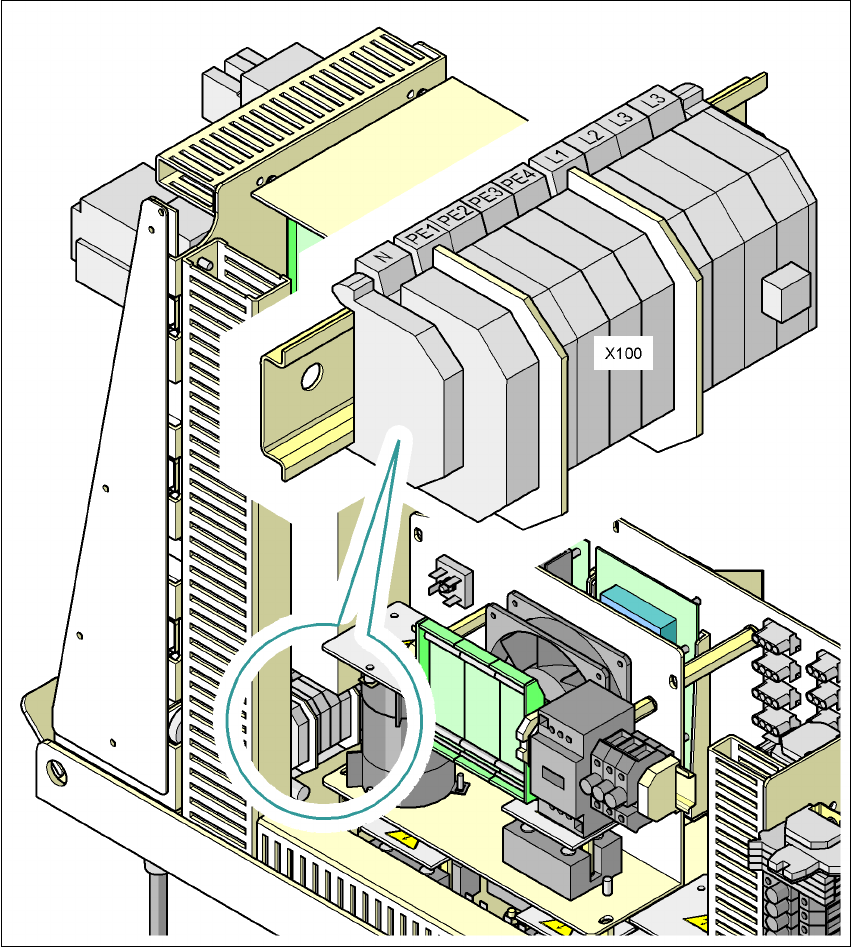
Fig. 4.3 - 4 Terminal panel for connecting the power cable
(L1) Three-phase
(L2) Three-phase
(L3) Three-phase
(N) Neutral conductor
(PE) Protective earth wires PE1, PE2, PE3, PE4
(X100) Terminal panel