X3_X4_Series machine - 第188页
4 Setting up and commissioning User manual SIPLACE X-Series 4.3 Infrastructure at t he installation location Software Version SR.601.x x 11/2005 US Edition 188 Æ Crimp a ferrule onto each end of t he wire. Æ Loosen th e …
User manual SIPLACE X-Series 4 Setting up and commissioning
Software Version SR.601.xx 11/2005 US Edition 4.3 Infrastructure at the installation location
187
4.3.3.4 Connecting the power supply cable
4
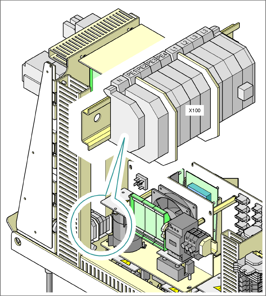
Fig. 4.3 - 4 Terminal panel for connecting the power cable
(L1) Three-phase
(L2) Three-phase
(L3) Three-phase
(N) Neutral conductor
(PE) Protective earth wires PE1, PE2, PE3, PE4
(X100) Terminal panel

4 Setting up and commissioning User manual SIPLACE X-Series
4.3 Infrastructure at the installation location Software Version SR.601.xx 11/2005 US Edition
188
Æ Crimp a ferrule onto each end of the wire.
Æ Loosen the nuts on the angled cable gland (item 2 in Fig. 4.3 - 3).
Æ Fold up the angled cable gland.
Æ Feed the power supply cable through the angled cable gland to the terminal panel X100 (see
X100 in Fig. 4.3 - 4
).
Æ Connect the cable to the terminal and ensure that it has a sufficient bending radius. The wires
must not be kinked.
Æ Fold up the angled cable gland (item 2 in Fig. 4.3 - 3) and tighten the nuts hand-tight.
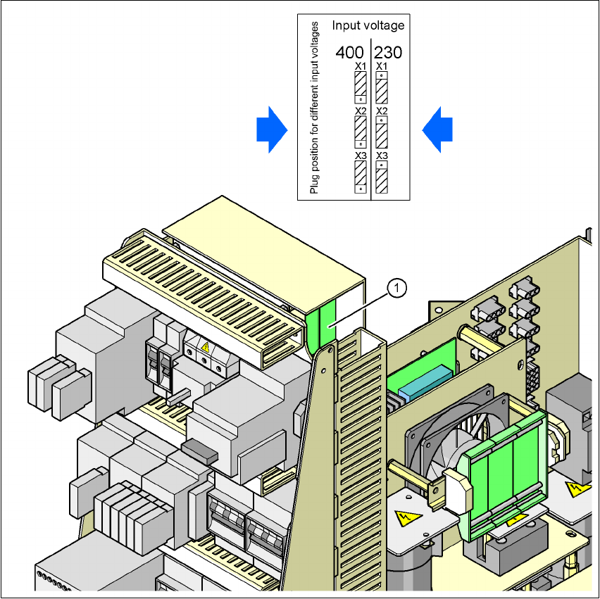
4.3.3.5 Checking the inrush current limitation jumpers
The inrush current limitation must be configured in relation to the supply voltage. This is done us-
ing plug-in jumpers on the inrush current limitation board (item 1 in Fig. 4.3 - 5
).
User manual SIPLACE X-Series 4 Setting up and commissioning
Software Version SR.601.xx 11/2005 US Edition 4.3 Infrastructure at the installation location
189
4
Fig. 4.3 - 5 Position of the board and connectors for the inrush current limitation
4
(1) Inrush current limitation board
X1, X2, X3 Connectors for configuring the inrush current limitation on the board
Æ Check the jumper assignment and correct if necessary.
3 x 380 VAC
3 x 400 VAC
3 x 415 VAC
3 x 208 VAC
3 x 230 VAC