X3_X4_Series machine - 第205页
User manual SIPLAC E X-Series 4 Setting up and commissioning Software Version SR.601.xx 11/2005 US Edition 4.4 Sett ing up the placement machine 205 Æ Introduce th e mandrel (ite m 5 in Fig. 4.4 - 9 ) of the c onveyor co…
4 Setting up and commissioning User manual SIPLACE X-Series
4.4 Setting up the placement machine Software Version SR.601.xx 11/2005 US Edition
204
4
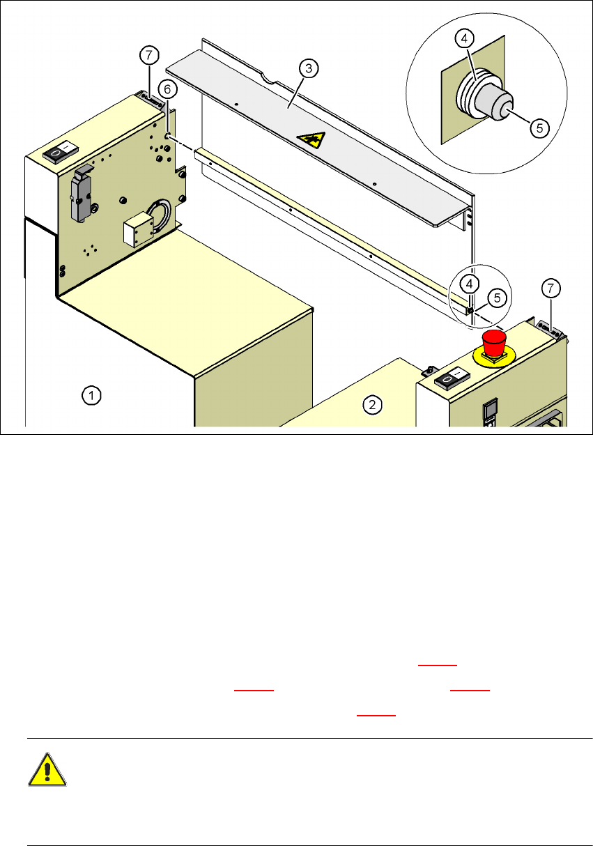
Fig. 4.4 - 9 Fitting the conveyor cover and the second half of the extension kit
(1) Half of the extension kit already fitted
(2) Second half of the extension kit to be fitted
(3) Conveyor cover
(4) Insert 3 white plastic washers on both sides
(5) Mandrel of the conveyor cover
(6) Hole
(7) Protective cover switch
Æ Push 3 white plastic washers onto each mandrel (item 5 in Fig. 4.4 - 9).
Æ Guide the mandrel (item 5 in Fig. 4.4 - 9) into the hole (item 6 in Fig. 4.4 - 9).
Æ Lift the second half of the extension kit (item 2 in Fig. 4.4 - 9) against the machine frame.
CAUTION 4
Make sure that this half of the extension kit does not collide with the hexagonal shaft of the
PCB conveyor and thus bend the shaft.

User manual SIPLACE X-Series 4 Setting up and commissioning
Software Version SR.601.xx 11/2005 US Edition 4.4 Setting up the placement machine
205
Æ Introduce the mandrel (item 5 in Fig. 4.4 - 9) of the conveyor cover into the hole (item 6 in Fig.
4.4 - 9
) in the second half of the extension kit.
Æ Position the second half of the extension kit so that the assembly bracket lies on the assembly
bar (item 7 in Fig. 4.4 - 8
).
Æ Fix the second half of the machine using 2 fillister head screws M6x16 and washers (item 3
in Fig. 4.4 - 8
).
4.4.7.3 Fixing the hexagonal shaft guide
Æ On the single conveyor, fix
one
guide for the hexagonal shaft (item 8 in Fig. 4.4 - 7) to the
extension kit using two fillister head screws M6x16 and washers.
Æ On the double conveyor, fix two guides for the hexagonal shaft (item 8 in Fig. 4.4 - 7) to the
extension kit using two fillister head screws M6x16 and washers.
4.4.7.4 Connecting the power cables - Extension kit on the PCB output side
4
4
4
4
4
Left-hand side of the extension kit
(viewed in the direction of travel)
Connector/cable To connector/cable
Emergency stop button
Start/Stop button
X63/03020687 X63/03002526
Protective cover switch, location 3
X53/03020409 X53/03002528
Button for the component trolley docking unit,
location 3
X232/03021056 X232/03021053
Right-hand side of the extension kit
(viewed in the direction of travel)
Connector/cable To connector/cable
Start/Stop button
Switch, PCB conveyor cover
X62/03020410 X62/03002525
Protective cover switch, location 2
X52/03006476 X52/03002527
Button for the component trolley docking unit,
location 2
X222/03021056 X222/03021052
4 Setting up and commissioning User manual SIPLACE X-Series
4.4 Setting up the placement machine Software Version SR.601.xx 11/2005 US Edition
206
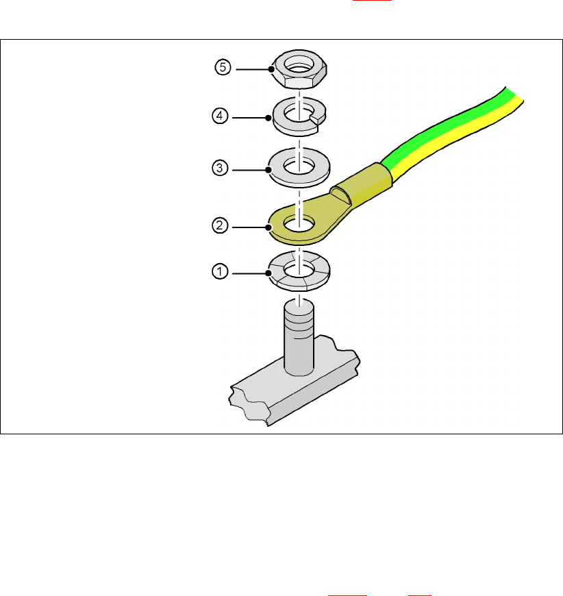
4.4.7.5 Fitting the grounding cable for the doors
Æ Fix the two grounding cables for the doors (item 4 in Fig. 4.4 - 8) to the machine frame as
follows:
4
Fig. 4.4 - 10 Fitting the grounding cable
4
4
4
4
4
4.4.7.6 Checking and setting the protective cover switch
Æ Check that the protective cover switch (item 7 in Fig. 4.4 - 9, page 204) is working correctly.
Æ Adjust the protective cover switch if necessary (see Service Manual).
Hex nut M5
Spring washer M5, DIN 7980
Washer M5, DIN 125
Cable lug, annular
Contact washer