X3_X4_Series machine - 第214页
4 Setting up and commissioning User manual SIPLACE X-Series 4.4 Setting up the placement machine Software Version SR.601.xx 11/2005 US E dition 214 4.4.8.7 F itting t he axis uni t Æ Carefull y lift the axis unit onto th…

User manual SIPLACE X-Series 4 Setting up and commissioning
Software Version SR.601.xx 11/2005 US Edition 4.4 Setting up the placement machine
213
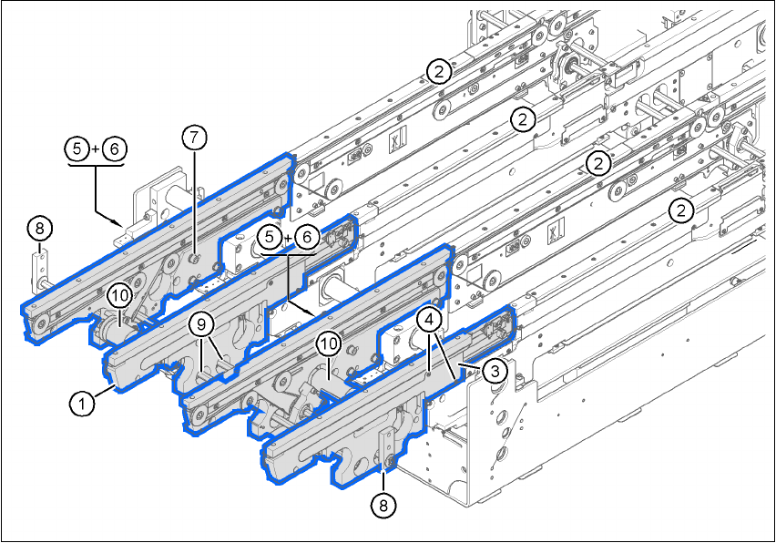
4.4.8.6 X4 axis unit (gantries 2 and 3) - Connecting the plugs
Æ Connect the power cable as shown in the following diagram:
4
4
Æ Check the switch settings for S1
1: ON
2: ON
X4 axis unit
Plugs
Connecting cable NOTE
Plug Cable
X21 X21
03009782
03009783
03009784
03009785
03009786 W1-W5
Secure connector with clips
X22 X22
03009802
03009803
03009804
03009805
03009807
Secure connector with clips
X4tr X4tr 03009780 Snap connector into place
X4tt X4tt 03009781 Snap connector into place
X4ur X4ur 03009800 Snap connector into place
X4ut X4ut 03009801 Snap connector into place
X1to
X3to
X5to
X1to
X3to
X5to
03009791
03009792
03009793
Insert as far as the stop
X1tp
X3tp
X5tp
X1tp
X3tp
X5tp
03009794
03009795
03009796
Insert as far as the stop
X1uo
X3uo
X5uo
X1uo
X3uo
X5uo
03009811
03009812
03009813
Insert as far as the stop
X1up
X3up
X5up
X1up
X3up
X5up
03009814
03009815
03009816
Insert as far as the stop
X30_1sq
X30_2sq
X30_1sq
X30_2sq
03010054
03010054
Screw tightly

4 Setting up and commissioning User manual SIPLACE X-Series
4.4 Setting up the placement machine Software Version SR.601.xx 11/2005 US Edition
214
4.4.8.7 Fitting the axis unit
Æ Carefully lift the axis unit onto the rail in the extension kit.
Æ Make sure that you do not squash any cables.
Æ Push the axis unit into the extension kit as far as the stop.
Æ Secure the axis unit with the fillister head screw.
Æ Insert the cover.
Æ Fix the grounding cable to the doors (item 2 in Fig. 4.4 - 8, page 202),
as shown in Fig. 4.4 - 10
on page 206.
Æ Lock the doors.
4.4.8.8 Fitting the side plates
Æ Fix the grounding cable to each side plate (item 6 in Fig. 4.4 - 8, page 202), as shown in Fig.
4.4 - 10
page 206.
Æ Fix the side plate to the machine frame with 6 fillister head screws.
PLEASE NOTE 4
If you have dismantled the output conveyor, continue from section 4.4.9
" Fitting the input con-
veyor" on page 215.
Once the input conveyor is fitted, then continue the assembly work from section 4.4.13
"Fitting
the main fault indicator" on page 230.
User manual SIPLACE X-Series 4 Setting up and commissioning
Software Version SR.601.xx 11/2005 US Edition 4.4 Setting up the placement machine
215
4.4.9 Fitting the input conveyor
4.4.9.1 Tools
– Allen keys, DIN 911, set
– Phillips screwdriver, size 1
4.4.9.2 Assembly
4
Fig. 4.4 - 15 Input conveyor - dual conveyor
(1) Panel, input conveyor
(2) Panel, processing conveyor 1
(3) Cable cover 20 x 200
(4) Countersunk screw, ISO 7046, M3x6, 2x per cable cover
(5) Cable cover 20 x 310
(6) Fillister head screw DIN 912, M3x5, 1x per cable cover
(7) Fillister head screw DIN 912, M6x16, and washer, 4x per panel
(8) Guide for hexagonal shaft
(9) Hexagonal shaft (single conveyor: one, dual conveyor: two)
(10) Drive unit