X3_X4_Series machine - 第217页
User manual SIPLAC E X-Series 4 Setting up and commissioning Software Version SR.601.xx 11/2005 US Edition 4.4 Sett ing up the placement machine 217 4.4.10 Fitting the extension kit on the PCB input side 4.4.10.1 T ools …

4 Setting up and commissioning User manual SIPLACE X-Series
4.4 Setting up the placement machine Software Version SR.601.xx 11/2005 US Edition
216
Æ Remove the cable covers (items 3 and 5 in Fig. 4.4 - 15) from the input conveyor (item 1 in
Fig. 4.4 - 15
).
Æ Carefully place the panel (item 1 in Fig. 4.4 - 15) against the panel on the processing con-
veyor (item 2 in Fig. 4.4 - 15
).
CAUTION 4
Be careful not to cut through any of the light barrier or drive motor cables.
Æ Fix each panel using 4 fillister head screws M6x16 and the associated washers (item 7 in Fig.
4.4 - 15
).
Æ Connect the power cable to the light barriers and drive motors.
Æ Fix the cable covers in place (item 3 and 5 in Fig. 4.4 - 15).
Æ Introduce the hexagonal shaft (item 9 in Fig. 4.4 - 15) into the drive unit (item 10 in Fig. 4.4 -
15).
Æ Make sure that the hexagonal shaft guide (item 8 in Fig. 4.4 - 15) always points towards the
conveyor side wall to which the drive unit (item 10 in Fig. 4.4 - 15
) is fixed.
User manual SIPLACE X-Series 4 Setting up and commissioning
Software Version SR.601.xx 11/2005 US Edition 4.4 Setting up the placement machine
217
4.4.10 Fitting the extension kit on the PCB input side
4.4.10.1 Tools
– Allen keys, DIN 911, set
– Machine key
4.4.10.2 Assembly
4
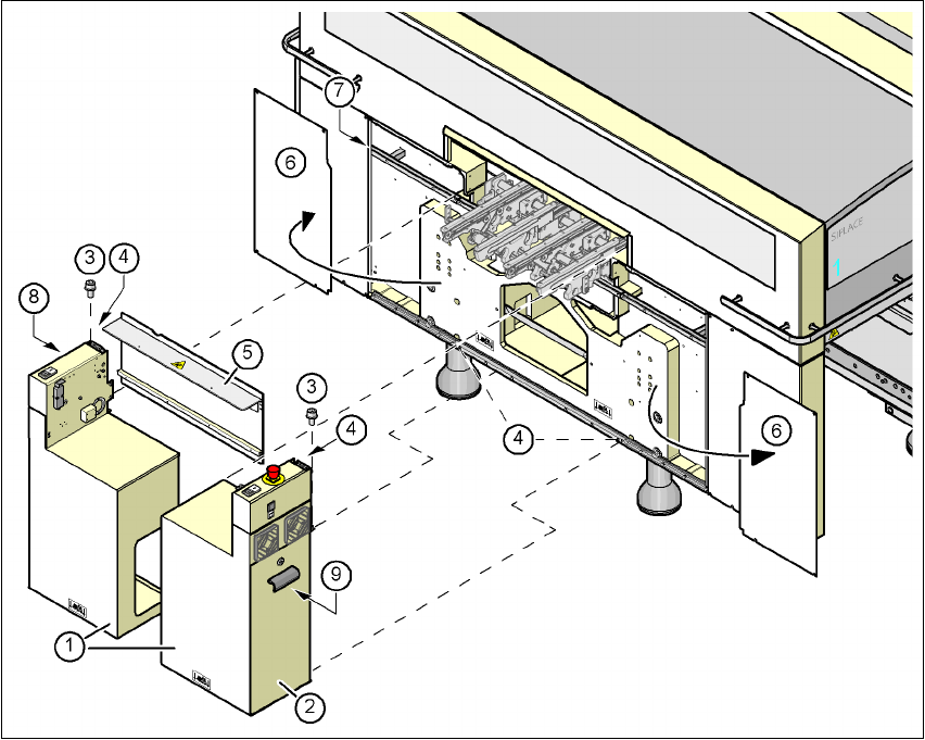
Fig. 4.4 - 16 Fitting the extension kit on the PCB input side
(1) Extension kit, dismantled
(2) Doors
(3) Fillister head screw DIN 912, M6x16 and washer
(4) Ground connection
(5) Conveyor cover
(6) Side plate, dismantled
(7) Drawer unit rail
(8) Computer unit
(9) Axis unit (X3, X4)
4 Setting up and commissioning User manual SIPLACE X-Series
4.4 Setting up the placement machine Software Version SR.601.xx 11/2005 US Edition
218
Æ Remove both side plates (item 6 in Fig. 4.4 - 16).
CAUTION 4
Do not unscrew the three bottom screws straight away. Simply loosen them so that the side
plate does not fall off.
Æ Detach the ground cable from the side plate.
Æ Remove both doors (item 2 in Fig. 4.4 - 16) from the extension kit (item 1).
PLEASE NOTE: 4
To avoid damage, we recommend that a second person helps to assemble the extension kit.
Æ Set down the computer unit (item 8 in Fig. 4.4 - 16) and the axis unit (item 9 in Fig 4.4 - 16)
at the side of the machine in order to make enough space to fit the extension kit (item 1 in Fig.
4.4 - 16
).
Æ Make sure that the connecting cables to the computer and axis units are not too tight.
Æ Lift one half of the extension kit (item 1 in Fig. 4.4 - 16) against the machine frame and position
it so that the assembly bracket lies on the assembly bar (item 7 in Fig. 4.4 - 16
).
CAUTION 4
Make sure that the extension kit does not collide with the hexagonal shaft of the PCB con-
veyor and thus become bent.
Æ Fix this half of the extension kit using 2 fillister head screws M6x16 and washers (item 3 in
Fig. 4.4 - 16
).
Æ
Before
assembling the second half of the extension kit, fit the conveyor cover (item 5 in Fig.
4.4 - 16
). The procedure is as follows: