X3_X4_Series machine - 第231页
User manual SIPLAC E X-Series 4 Setting up and commissioning Software Version SR.601.xx 11/2005 US Edition 4.4 Sett ing up the placement machine 231 4 Fig. 4.4 - 23 Fitting the main indicat or lamp 4 (1) Main indic ator …

4 Setting up and commissioning User manual SIPLACE X-Series
4.4 Setting up the placement machine Software Version SR.601.xx 11/2005 US Edition
230
4.4.12.3 Fitting the X3, X4 axis unit (gantry 1 and gantry 4)
Æ Carefully lift the axis unit onto the rail in the extension kit.
Æ Make sure that you do not squash any cables.
Æ Push the axis unit into the extension kit as far as the stop.
Æ Secure the axis unit with the fillister head screw.
Æ Insert the cover.
Æ Fix the grounding cable to the doors (item 2 in Fig. 4.4 - 16, page 217),
as shown in Fig. 4.4 - 18
on page 221.
Æ Lock the doors.
4.4.12.4 Fitting the side plates
Æ Fix the grounding cable to each side plate (item 5 in Fig. 4.4 - 16, page 217),
as shown in Fig. 4.4 - 18
page 221.
Æ Fix the side plate to the machine frame with 6 fillister head screws.
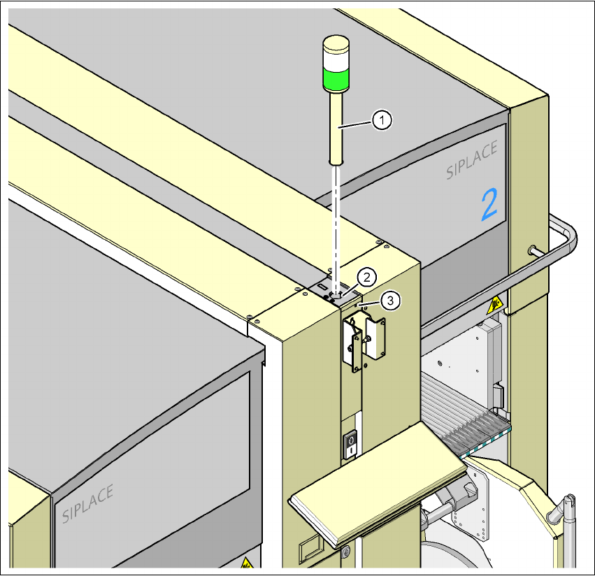
4.4.13 Fitting the main fault indicator
Æ Connect the main fault indicator cables to the cables on the basic machine.
Æ Insert the main fault indicator lamp into the hole (item 2 in Fig. 4.4 - 23) until the tube of the
lamp projects sufficiently into the terminal beneath.
Æ Tighten the hexagon socket head screw beneath the hole (item 3 in Fig.4.4 - 23).
User manual SIPLACE X-Series 4 Setting up and commissioning
Software Version SR.601.xx 11/2005 US Edition 4.4 Setting up the placement machine
231
4
Fig. 4.4 - 23 Fitting the main indicator lamp
4
(1) Main indicator lamp
(2) Hole for the main indicator lamp
(3) Hole for the locking screw
4.4.14 Fixing the monitors
Æ Fix the monitors and connect the cables.
Æ Check the cable connections
4 Setting up and commissioning User manual SIPLACE X-Series
4.4 Setting up the placement machine Software Version SR.601.xx 11/2005 US Edition
232
4.4.15 Integrating the placement machine into the line
Æ Note the warning instructions described in section 4.4.2, page 190.
Æ The tools and equipment are listed in section 4.4.1, page 190.
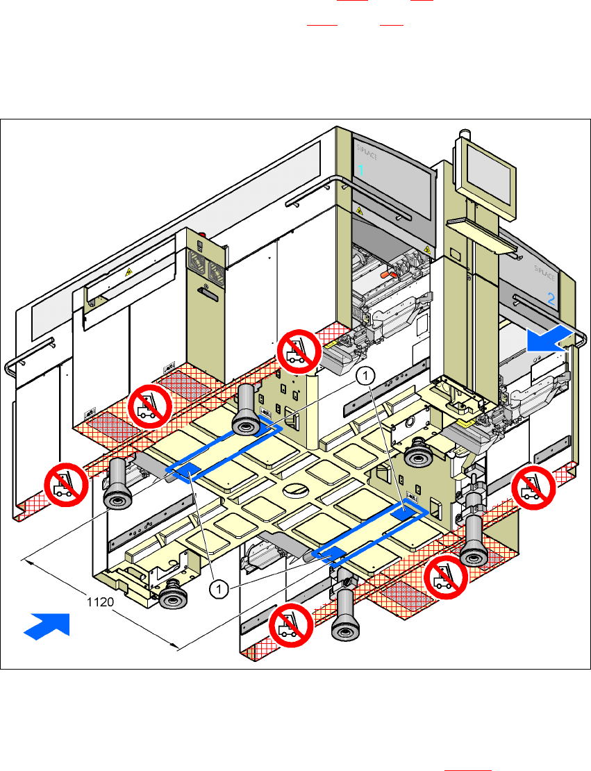
4.4.15.1 Positioning the fork-lift
4
Fig. 4.4 - 24 Contact surfaces - Forks across the direction of PCB transport
(1) Contact surfaces for the forks of the fork-lift
Æ Position the fork-lift across the direction of PCB transport and open the forks far enough so
that the machine's contact surface lies evenly on the forks (see Fig. 4.4 - 24
).