X3_X4_Series machine - 第234页
4 Setting up and commissioning User manual SIPLACE X-Series 4.4 Setting up the placement machine Software Version SR.601.xx 11/2005 US E dition 234 4.4.15.3 Align ing the placement machine wit h respect to the line Æ Pos…

User manual SIPLACE X-Series 4 Setting up and commissioning
Software Version SR.601.xx 11/2005 US Edition 4.4 Setting up the placement machine
233
WARNING 4
Please note the following points
before
you raise the placement machine in order to avoid irre-
versible damage to the machine:
– The distance between the forks must be between 800 and 900 mm. The attachment surfaces
for the fork-lift are shown in Fig. 4.2 - 4
. The maximum distance between the contact surfaces
is 1120 mm. NEVER increase the distance between the forks so that the machine is lifted on
the side parts of the machine frame, since this would deform the machine frame.
Æ Make sure that the forks are evenly loaded when you lift the machine. A firm support between
the forks and placement machine will prevent the machine tilting when it is raised. This will
also prevent a one-sided load on the machine feet, which would deform the fixing of the ma-
chine feet. We recommend that a second person watch the machine as it is raised, and make
sure that the machine does not tip to one side when lifted with the fork-lift.
4.4.15.2 Points that MUST be noted when transporting the machine
WARNING 4
When you are transporting the machine, make sure that
all
the feet are clear of the floor. If they
are not clear, the feet will drag along the floor or bump into obstacles. This could damage the
machine foot fixing in the machine frame.
4 Setting up and commissioning User manual SIPLACE X-Series
4.4 Setting up the placement machine Software Version SR.601.xx 11/2005 US Edition
234
4.4.15.3 Aligning the placement machine with respect to the line
Æ Position the placement machine on the free location on the line using the fork-lift.
WARNING 4
Lower the placement machine slowly. A second person should look underneath to ensure
that all the machine foot touch the floor at the same time. If the machine feet on one side hit
the ground hard, the fixings may be damaged.
4
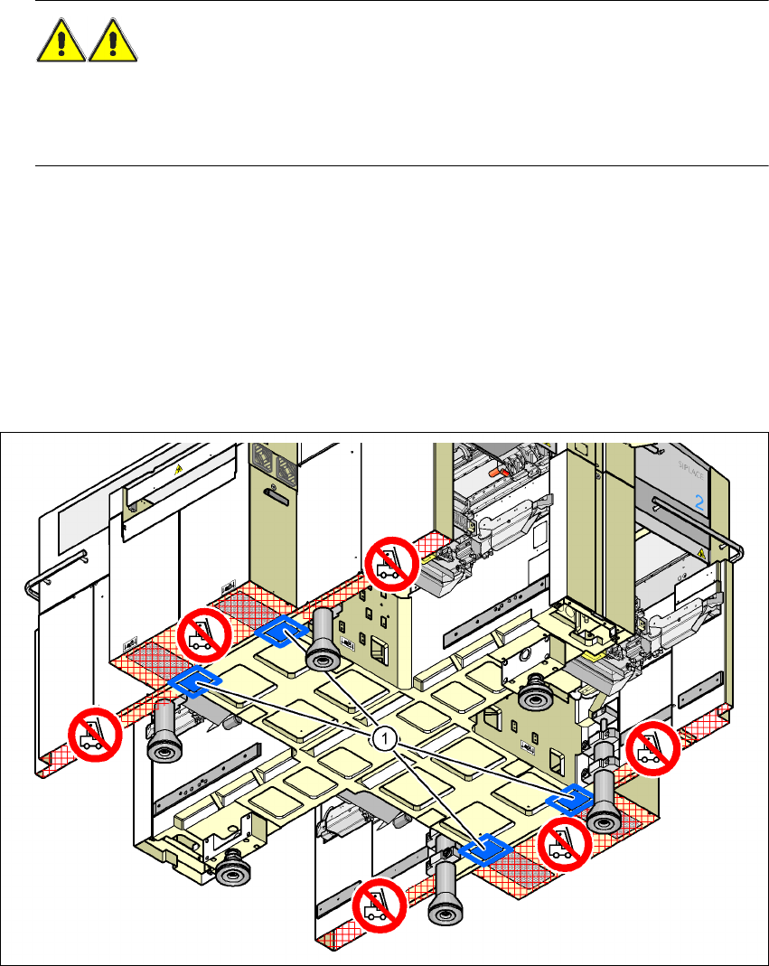
4.4.15.4 Aligning the placement machine with the air cushion transport system
Æ Place the four air cushions of the air cushion transport system beneath the machine frame.
Æ Raise the placement machine and align it with respect to the line.
Æ Check the distance from the PCB conveyor system of the adjacent machine. It should be be-
tween 1 mm and 3 mm.
Æ Lower the placement machine.
4
Fig. 4.4 - 25 Contact positions for the air cushion transport system
(1) Contact surfaces for the air cushion transport system
User manual SIPLACE X-Series 4 Setting up and commissioning
Software Version SR.601.xx 11/2005 US Edition 4.4 Setting up the placement machine
235
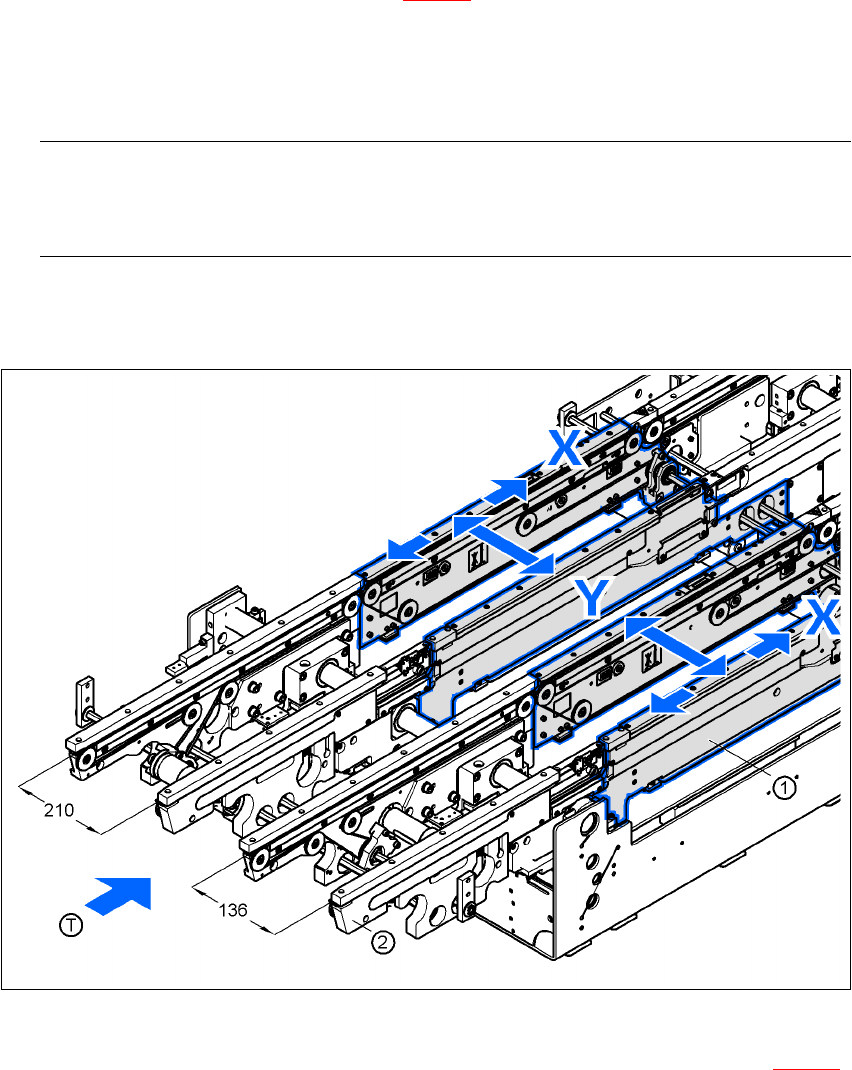
4.4.16 Making final adjustments to the placement machine
Æ Place the machine's spirit level on the panels of the PCB conveyor in placement area 1 in
both the X and the Y directions (see Fig. 4.4 - 26
). The PCB conveyor width is preset:
Single conveyor 210 mm
Dual conveyor, track 1 136 mm
Dual conveyor, track 2 210 mm 4
PLEASE NOTE: 4
On the dual conveyor, place the spirit level only on the outer panels of the machine for ad-
justing in the X direction.
Æ Measure the distance between the top edge of the PCB conveyor belt and the floor. This dis-
tance should be 800 mm, 900 mm, 930 mm or 950 mm.
4
Fig. 4.4 - 26 Adjusting the placement machine in the X and Y directions
Æ Use the size 36 fork wrench to adjust the adjusting screw M24x2x120 (item 1 in Fig. 4.4 - 27)
so that the label on the machine spirit level does not deviate from the zero point for the re-
quired PCB transport height.