X3_X4_Series machine - 第240页
4 Setting up and commissioning User manual SIPLACE X-Series 4.5 Adapting the SI PLACE X- series component trolley to the PCB transport height Software V ersion SR.601.xx 11/2005 US E dition 240 4 Fig. 4.5 - 2 Fixing the …
User manual SIPLACE X-Series 4 Setting up and commissioning
Software Version SR.601.xx 11/2005 US Edition 4.5 Adapting the SIPLACE X-series component trolley to the PCB transport height
239
Æ Always follow the applicable accident prevention regulations.
Æ Remove all the feeder modules from the component table, if you want to adjust the height for
the component feeder table.
4.5.2 Tools and equipment
You will need the following tools and equipment to adjust the height of the component trolley:
– Hammer
– Punch, 8 mm
– Assembly guide (item no. 03015976-xx)
– Lifting device for raising the component trolley table, carrying capacity at least 80 kg
4.5.3 Changing the component trolley height
WARNING 4
Æ Remove all the feeder modules from the component table.
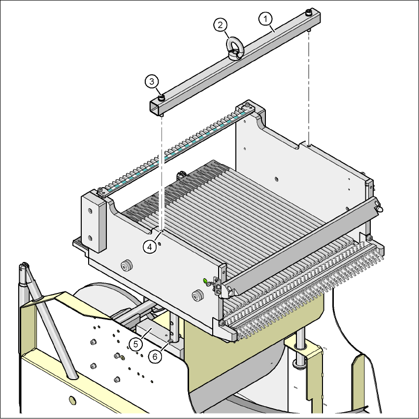
Æ Fit the assembly guide to the component table in order to adjust the height. This prevents the
component table becoming deformed when the table is raised or lowered.
Æ Fix the assembly guide (item 1 in Fig. 4.5 - 2) to the component table (item 4 in Fig. 4.5 - 2)
using the two hexagon socket head screws M8 x 50 (item 3 in Fig. 4.5 - 2
).
Æ Attach the hooks of the lifting device to the eye (item 2 in Fig. 4.5 - 2).
Æ Raise the component trolley bed slightly to expose the split pins (item 6 in Fig. 4.5 - 2).
Æ Use the punch to carefully tap out the split pins on both sides.
Æ Insert the spiral clamping pins into the holes for the required PCB conveyor height (see Fig.
4.5 - 1
).
Æ Lower the component trolley bed slowly until the split pins lie on the supporting blocks (item
5 in Fig. 4.5 - 2
).
Æ Dismantle the assembly guide
4 Setting up and commissioning User manual SIPLACE X-Series
4.5 Adapting the SIPLACE X-series component trolley to the PCB transport height Software Version SR.601.xx 11/2005 US Edition
240
4
Fig. 4.5 - 2 Fixing the assembly guide to the component table of the SIPLACE X component trolley
(1) Assembly guide
(2) Eye
(3) Hexagon socket head screw DIN 912, M8 x 50, 2 x
(4) M8 threaded hole in the component table, 2x
(5) Supporting block, 2x
(6) Split pin, DIN 7343, 8 x 40 - St, 2 x
User manual SIPLACE X-Series 4 Setting up and commissioning
Software Version SR.601.xx 11/2005 US Edition 4.6 Adapting the length of the SIPLACE X used tape chute to the PCB conveyor height
241
4.6 Adapting the length of the SIPLACE X used tape chute
to the PCB conveyor height
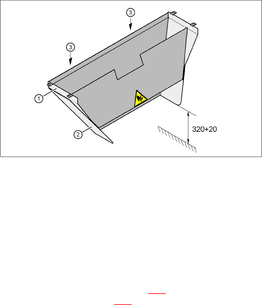
Depending on the PCB conveyor height, the length of the used tape chute can be set so that the
pieces of tape are diverted directly into the reject bin of the component trolley.
4
Fig. 4.6 - 1 Adapting the length of the used tape chute (X-series) - Dimensions in millimeters
(1) Used tape chute
(2) Extension
(3) Hexagonal nut M4, DIN 985, 2 x
4.6.1 Tools
– Fork wrench, size 7
4.6.2 Setting the length of the used tape chute
4.6.2.1 830 mm PCB conveyor height
Æ Loosen the two M4 hexagonal nuts (item 3 in Fig. 4.6 - 1).
Æ Remove the extension (item 2 in Fig. 4.6 - 1).