X3_X4_Series machine - 第241页
User manual SIPLAC E X-Series 4 Setting up and commissioning Software Vers ion SR.601.xx 11/ 2005 US Ed ition 4.6 Adapting the length of the S IPLACE X us ed tape chute to t he PCB conv eyor height 241 4.6 Adapti ng the …
4 Setting up and commissioning User manual SIPLACE X-Series
4.5 Adapting the SIPLACE X-series component trolley to the PCB transport height Software Version SR.601.xx 11/2005 US Edition
240
4
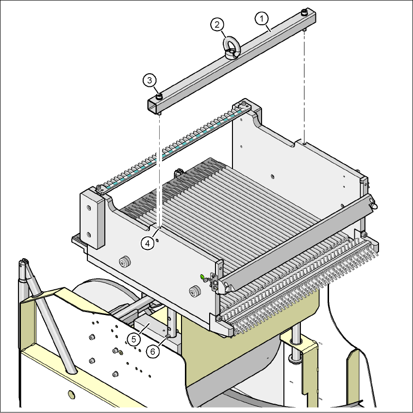
Fig. 4.5 - 2 Fixing the assembly guide to the component table of the SIPLACE X component trolley
(1) Assembly guide
(2) Eye
(3) Hexagon socket head screw DIN 912, M8 x 50, 2 x
(4) M8 threaded hole in the component table, 2x
(5) Supporting block, 2x
(6) Split pin, DIN 7343, 8 x 40 - St, 2 x
User manual SIPLACE X-Series 4 Setting up and commissioning
Software Version SR.601.xx 11/2005 US Edition 4.6 Adapting the length of the SIPLACE X used tape chute to the PCB conveyor height
241
4.6 Adapting the length of the SIPLACE X used tape chute
to the PCB conveyor height
Depending on the PCB conveyor height, the length of the used tape chute can be set so that the
pieces of tape are diverted directly into the reject bin of the component trolley.
4
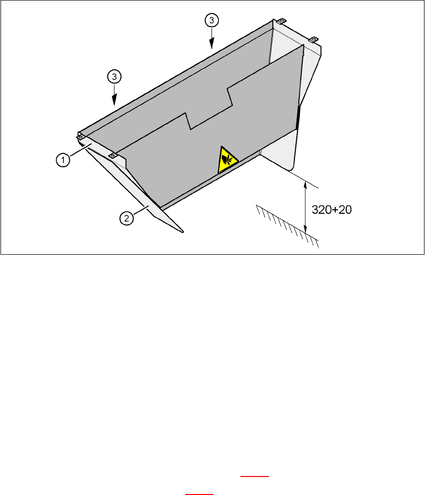
Fig. 4.6 - 1 Adapting the length of the used tape chute (X-series) - Dimensions in millimeters
(1) Used tape chute
(2) Extension
(3) Hexagonal nut M4, DIN 985, 2 x
4.6.1 Tools
– Fork wrench, size 7
4.6.2 Setting the length of the used tape chute
4.6.2.1 830 mm PCB conveyor height
Æ Loosen the two M4 hexagonal nuts (item 3 in Fig. 4.6 - 1).
Æ Remove the extension (item 2 in Fig. 4.6 - 1).

4 Setting up and commissioning User manual SIPLACE X-Series
4.6 Adapting the length of the SIPLACE X used tape chute to the PCB conveyor height Software Version SR.601.xx 11/2005 US Edition
242
4.6.2.2 900 mm - 950 mm PCB transport heights
Æ Loosen the two M4 hexagonal nuts (item 3 in Fig. 4.6 - 1).
Æ Adjust the extension (item 2 in Fig. 4.6 - 1) so that the distance between the bottom edge and
the floor does not exceed 320 mm + 20 mm (see Fig. 4.6 - 1
).