X3_X4_Series machine - 第251页
User manual SIPLAC E X-Series 5 Tasks on the machine Software Vers ion SR.601.xx 11/ 2005 US Ed ition 5.3 Carrying out a walk-through inspe ction 251 5.3 Car rying out a walk-thr ough inspection 5.3.1 Checking the feed e…

5 Tasks on the machine User manual SIPLACE X-Series
5.2 Changing shift Software Version SR.601.xx 11/2005 US Edition
250
5.2 Changing shift
Æ Splice the tapes early. The feeder modules do not have to be refilled as soon as the new shift
starts. This avoids extended down times.
Æ At the shift change, pass important information on to the next operator. This includes, for in-
stance, changes to the placement program. Also read through the list of the descriptions of
the steps to take in section 5.7
.
Æ Carry out a set-up check.
Make sure that the feeder modules are equipped with the correct components and that they
are at the correct locations in the component trolley.
PLEASE NOTE
Hand over the line in the same state that you would want to find it in when starting your shift.
This means that: 5
– The rejection containers are empty.
– The waste containers are empty.
– The feeder areas have been carefully cleaned with a vacuum cleaner.
User manual SIPLACE X-Series 5 Tasks on the machine
Software Version SR.601.xx 11/2005 US Edition 5.3 Carrying out a walk-through inspection
251
5.3 Carrying out a walk-through inspection
5.3.1 Checking the feeder modules (X-series)
5
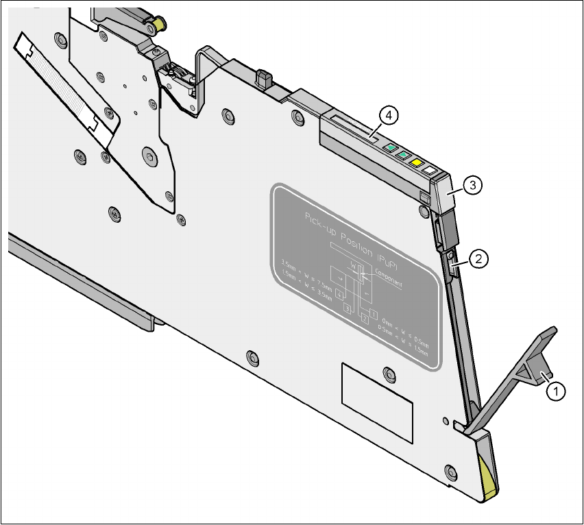
Fig. 5.3 - 1 Checking the X feeder modules
(1) Flap
(2) Blade
(3) Status display
(4) LCD display
5
Æ Check to see whether the tape foil removal container for the X tape feeder module is full.
Open the flap (item 1). Pull out the cover foil and cut it with scissors or on the integral blade
(item 2) on 8 and 12 mm X tape feeder modules.
5 Tasks on the machine User manual SIPLACE X-Series
5.3 Carrying out a walk-through inspection Software Version SR.601.xx 11/2005 US Edition
252
PLEASE NOTE 5
Never tear the cover foil. This can cause problems with the cover foil pull-off. There is an in-
tegral blade (item 2) for easily cutting the on the 8 and 12 mm X tape feeder modules.
Æ Check the multicolor status display (item 3 in Fig. 5.3 - 1).
– If it lights up green, the feeder module is on standby.
– If it lights up orange, it is signaling a warning. The text of the warning appears on the LCD
display (item 4 in Fig. 5.3 - 1
).
– If the status display lights up red, a malfunction has occurred. The error message ap-
pears on the LCD display (item 3 in Fig. 5.3 - 1
).
A list of the LCD and status displays on the operator panel is given in section 5.6
, page
268
. 5
If the status display is off, the cause may be as follows: 5
– The feeder module is not in the current set-up.
– The feeder module is defective.
– The feeder module has been disabled (due to a drop in pressure, for example)
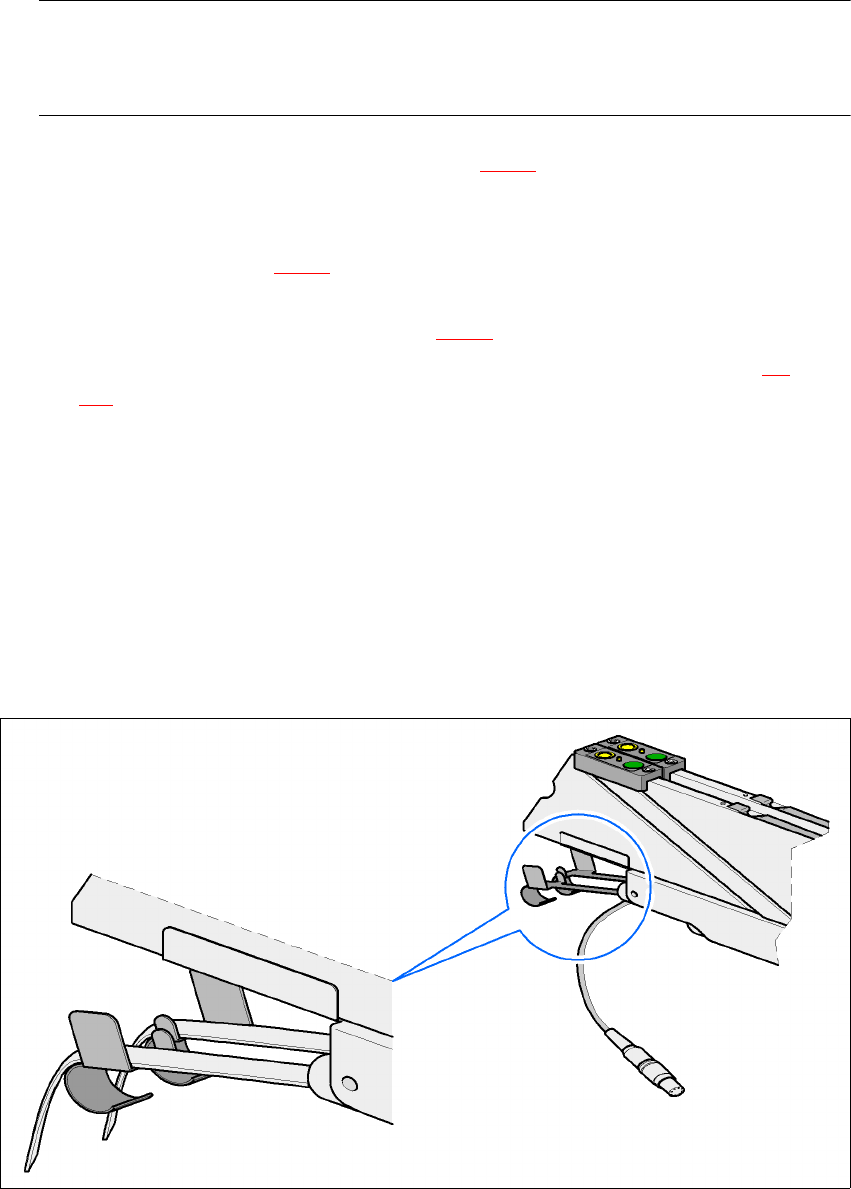
5.3.2 Checking the S feeder modules
Æ Make sure that the tape is correctly placed in the springs of the S feeder module.
5
Fig. 5.3 - 2 Placing the tape in the springs of the S feeder module