X3_X4_Series machine - 第264页
5 Tasks on the machine User manual SIPLAC E X-Series 5.4 Setting up the feeder modules Software Version SR.601.xx 11/2005 US Edition 264 Æ Push the lever (i tem 5 in Fig . 5.4 - 5 ) forwar d in orde r to raise the pick -…
User manual SIPLACE X-Series 5 Tasks on the machine
Software Version SR.601.xx 11/2005 US Edition 5.4 Setting up the feeder modules
263
5
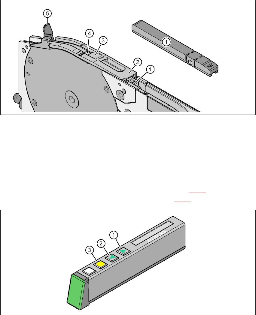
Fig. 5.4 - 5 Pick-up window on the tape feeder module
(1) Tape support, removable
(2) Pick-up window
(3) Removal edge for the cover foil
(4) Component pick-up area
(5) Lever for raising and latching the pick-up window
Æ On the operator panel, press the FORWARD button (item 1 in Fig. 5.4 - 6) until the bend of
the cover foil is in the component pick-up area (item 4 in Fig. 5.4 - 5
).
5
Fig. 5.4 - 6 Operator panel of the feeder module
(1) FORWARD button for moving the component tape forward
(2) BACK button for moving the component tape back
(3) FOIL button for tensioning the cover foil
5 Tasks on the machine User manual SIPLACE X-Series
5.4 Setting up the feeder modules Software Version SR.601.xx 11/2005 US Edition
264
Æ Push the lever (item 5 in Fig. 5.4 - 5) forward in order to raise the pick-up window (item 2 in
Fig. 5.4 - 5
) into the first latching position.
Æ Pull the cover foil at the side of the pick-up window forward and out underneath the pick-up
window.
Æ Fold the cover foil back until it lies against the pull-off edge (item 3 in Fig. 5.4 - 5).
PLEASE NOTE 5
Do not lower the pick-up window until the cover foil is lying against the pull-off edge.
Æ Push the lever (item 5 in Fig. 5.4 - 5) back to lower the pick-up window.
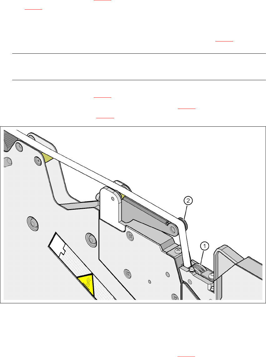
Æ Guide the cover foil over the cover foil rocker (item 2 in Fig. 5.4 - 7) until it reaches the foil
packing wheels (item 1 in Fig. 5.4 - 7
).
5
Fig. 5.4 - 7 Guiding the cover foil to the foil packing wheels
(1) Cover foil packing wheels
(2) Cover foil
5
Æ On the operator panel, press the FOIL button (item 3 in Fig. 5.4 - 6) until the cover foil is ten-
sioned. The cover foil rocker points down and stops the drive motor.
Æ Cut the component tape flush with the front end of the feeder module.
User manual SIPLACE X-Series 5 Tasks on the machine
Software Version SR.601.xx 11/2005 US Edition 5.4 Setting up the feeder modules
265
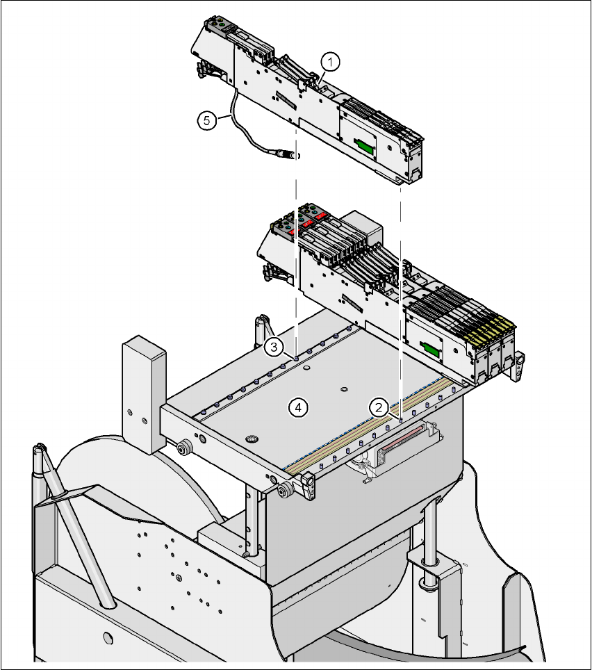
5.4.5 Using the S feeder module on the component trolley (HF-series)
5
Fig. 5.4 - 8 Component trolley (HF-series) with 15 locations for S feeder modules
(1) S feeder module
(2) Centering pin
(3) Centering ball
(4) Component feeder table
(5) Connecting cable for the S feeder module