X3_X4_Series machine - 第275页
User manual SIPLAC E X-Series 5 Tasks on the machine Software Vers ion SR.601.xx 11/ 2005 US Ed ition 5.10 Dock ing the component trolley in or out 275 5.10 Docking th e component troll e y in o r out 5.10.1 Safety instr…

5 Tasks on the machine User manual SIPLACE X-Series
5.9 Refilling components Software Version SR.601.xx 11/2005 US Edition
274
5.9 Refilling components
The online help contains information on refilling components with and without barcodes.
Æ With tape feeder modules, make sure that you always splice on a new tape early enough so
that the feeder modules do not run out of components.
Æ However, do not splice the tapes too early because if you wind the tape onto the new reel
after splicing the end of the old tape, the reel with the new tape may be overfilled. The tape
could then slip off the reel and become tangled. Under certain circumstances, this could
cause pick-up errors and prolonged down times.
Æ Always insert spindles when using tape reels of 15" (381 mm) and larger (see Fig. 5.3 - 5)
and make sure that the separating plates are inserted correctly (see Fig. 5.3 - 4
).
User manual SIPLACE X-Series 5 Tasks on the machine
Software Version SR.601.xx 11/2005 US Edition 5.10 Docking the component trolley in or out
275
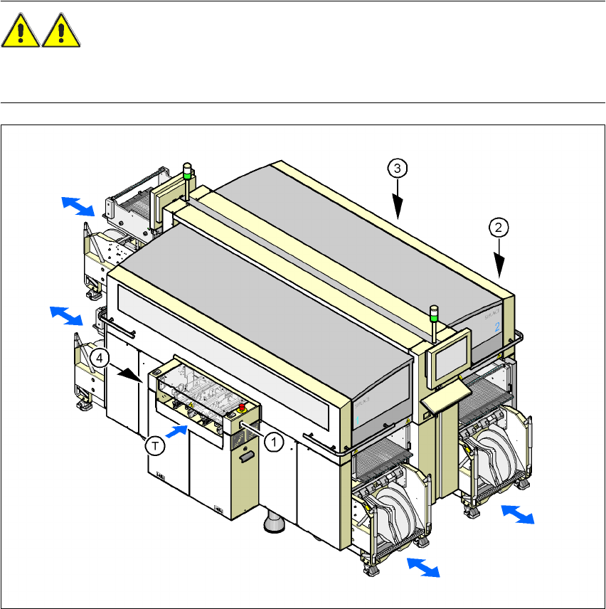
5.10 Docking the component trolley in or out
5.10.1 Safety instructions for docking component trolleys in and out
WARNING 5
To prevent accidents (risk of crushing), the component trolley may only be docked in or out by
one person.
5
Fig. 5.10 - 1 Safety instructions for docking the component trolley in or out
(1) Button for docking the component trolley in or out, location 1
(2) Button for docking the component trolley in or out, location 2
(3) Button for docking the component trolley in or out, location 3
(4) Button for docking the component trolley in or out, location 4
(T) Direction of PCB transport
5 Tasks on the machine User manual SIPLACE X-Series
5.10 Docking the component trolley in or out Software Version SR.601.xx 11/2005 US Edition
276
The safety concept for the component trolley change requires the operator to press a button (item
1, 2, 3 or 4 in Fig 5.10 - 1
) on the input or output side of the machine in order to dock the compo-
nent trolley in or out. This ensures that the operator is always standing to the side of the placement
machine. In addition, the component trolley can only be docked in if the protective covers are
closed.
5.10.2 Docking out the component trolley
Æ Click on the STOP PROCESSING PCB icon in the MAIN VIEW menu.
The PCB in progress will be completed. The icons of the SINGLE FUNCTIONS menu will
then be activated. 5
Æ Click on the desired icon SINGLE FUNCTIONS GANTRY.
Æ Select GANTRY FUNCTIONS.
Æ From this menu, click on the GO TO SET-UP POSITION button.
All the placement heads will move across the PCB conveyor to prevent them being damaged
when the component trolley is changed. 5
Æ Press the relevant button on the input or output side of the machine (item 1, 2, 3 or 4 in Fig.
5.10 - 1
) until the trolley is docked out fully.
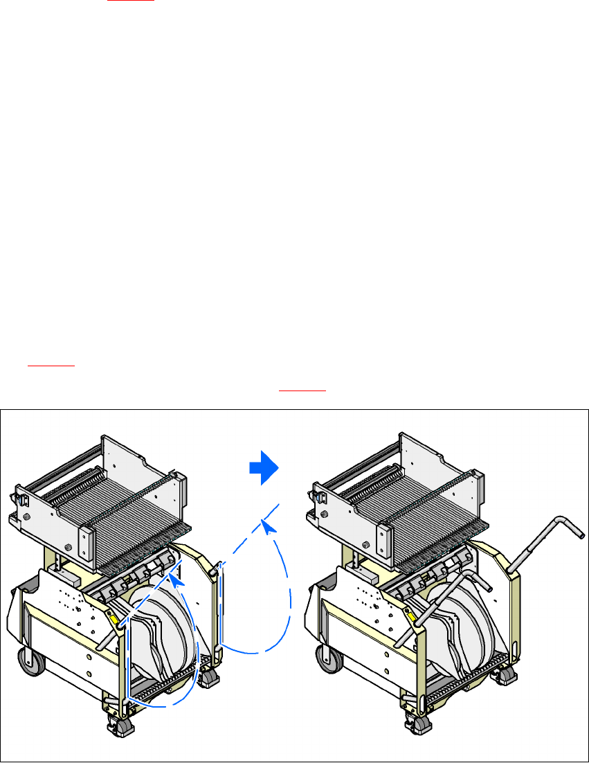
Æ Swivel the two handles up (item 1 in Fig. 5.10 - 2).
5
Fig. 5.10 - 2 Component trolley - swivel handles up to push
5
Æ With both hands on the handles, pull the component trolley out of the placement machine.