X3_X4_Series machine - 第282页
5 Tasks on the machine User manual SIPLAC E X-Series 5.10 Docking the component trolley in or out Software V ersion SR.601.xx 11/2005 US E dition 282 CAU TIO N 5 Check tha t the plac ement head is outside t he range o f …
User manual SIPLACE X-Series 5 Tasks on the machine
Software Version SR.601.xx 11/2005 US Edition 5.10 Docking the component trolley in or out
281
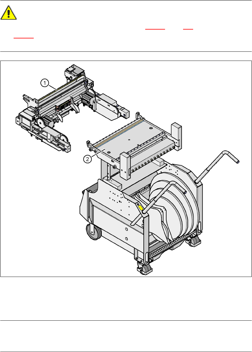
5.10.6 Docking the HF component trolley
CAUTION 5
The component trolleys for the SIPLACE X-series (Fig. 5.10 - 3
, page 278) and SIPLACE HF
(Fig. 5.10 - 6
) have different docking units. Each component trolley must therefore only be
docked into the correct docking unit.
5
Fig. 5.10 - 6 Component trolley and component trolley docking unit, SIPLACE HF
(1) Component trolley docking unit, SIPLACE HF
(2) Component trolley, SIPLACE HF
PLEASE NOTE 5
Shorten the component tapes on the front end of the S feeder modules to approximately 3 cm
before you dock in the component trolley.
5 Tasks on the machine User manual SIPLACE X-Series
5.10 Docking the component trolley in or out Software Version SR.601.xx 11/2005 US Edition
282
CAUTION 5
Check that the placement head is outside the range of the component trolley.
Æ Carefully push the component trolley into machine as far as the stop.
PLEASE NOTE 5
Close the protective covers since the component trolley can only be docked in if the covers are
closed.
Æ Press the relevant button on the input or output side of the machine (item 1, 2, 3 or 4 in Fig.
5.10 - 1
, page 275), until the trolley is docked in fully.
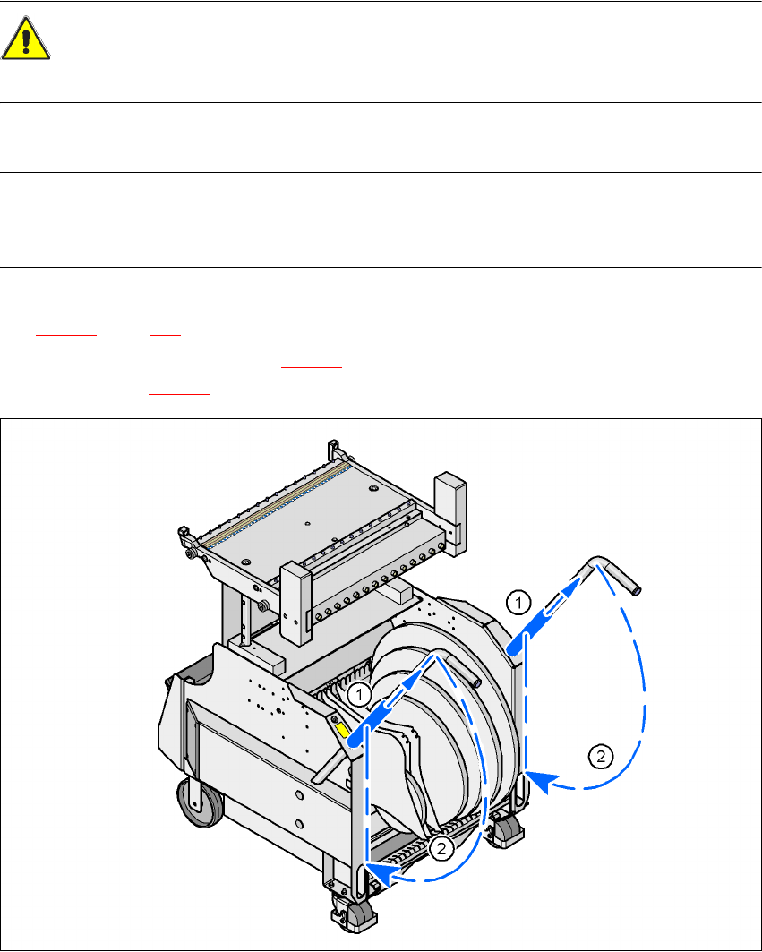
Æ Push the sleeve (item 1 in Fig. 5.10 - 7) up using both handles and swivel the handle down
(item 2 in Fig. 5.10 - 7
).
5
Fig. 5.10 - 7 HF component trolley - swivel handles down
(1) Push sleeve up
(2) Fold handle down
User manual SIPLACE X-Series 5 Tasks on the machine
Software Version SR.601.xx 11/2005 US Edition 5.11 Note operating status indicator lamp
283
5.11 Note operating status indicator lamp
The indicator lamp is used to signal operating statuses and malfunctions of the placement system.
5.11.1 Description of the functions
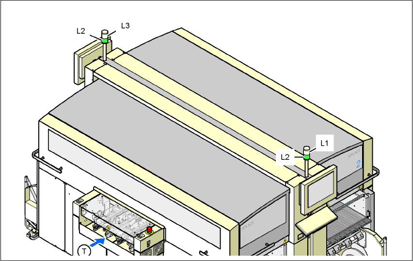
Fig. 5.11 - 1 Operating status indicator lamp
L1 Fault indicator lamp (white, right)
L2 Operating status indicator lamp (green, both lamps switched in parallel)
L3 Fault indicator lamp (white, left)
T Direction of PCB transport
5.11.2General operating statuses
–
Operating status indicator lamp (green) on continuously
The placement system is in service.
–
Operating status indicator lamp (green) flashes
The placement system is waiting for a PCB on the input belt or the placement system is wait-
ing until the output belt is free.
–
Right white fault indicator lamp L1 flashes
One or more tracks are empty on the right-hand side of the placement system. The placement
system continues to place any remaining components.