X3_X4_Series machine - 第289页
User manual SIPLAC E X-Series 6 Component han dling Software Version SR.601.xx 11/2005 US Edition 6.1 X feeder modules for the component trolley from the SIPLACE X- series 289 6.1.1.4 Design of the t ape feeder module fo…

6 Component handling User manual SIPLACE X-Series
6.1 X feeder modules for the component trolley from the SIPLACE X-series Software Version SR.601.xx 11/2005 US Edition
288
For 8 mm paper tapes, the paper thickness must not exceed 1.6 mm. The length of a component
pocket in the direction of travel must not exceed 51 mm.
6.1.1.2 Tape reel diameter
The tape reel diameter may be up to 19" (483 mm) for all feeder modules. A list of the maximum
tape reel diameters in relation to the PCB conveyor height can be found in section 6.2.7.2
, page
315
. For a tape reel diameter of 15" (381 mm) or more, the tape reels should be stored on spin-
dles.
6.1.1.3 Tape feeder module shapes for the SIPLACE X-series
In general, the tape feeder modules from the X series are approx. 587 mm long and approx.
200 mm high. The width and the number of locations that it fills on the component table are listed
in the following table.
6
The maximum height of any edges protruding over the top edge of the tape pocket is ≤ 3 mm.
Since the feeder modules do not have any raised flaps and are firmly anchored to the component
table, the risk of a head crash is minimized.
Tape feeder
modules
Feeder module width in
millimeters
Feeder module locations
required on the component table
8 mm X 10,8 1
12 mm X 22,6 2
16 mm X 34,4 3
24 mm X 34,4 3
32 mm X 46,2 4
44 mm X 58,0 5
56 mm X 69,8 6
72 mm X 81,6 7
88 mm X 105,2 9
User manual SIPLACE X-Series 6 Component handling
Software Version SR.601.xx 11/2005 US Edition 6.1 X feeder modules for the component trolley from the SIPLACE X-series
289
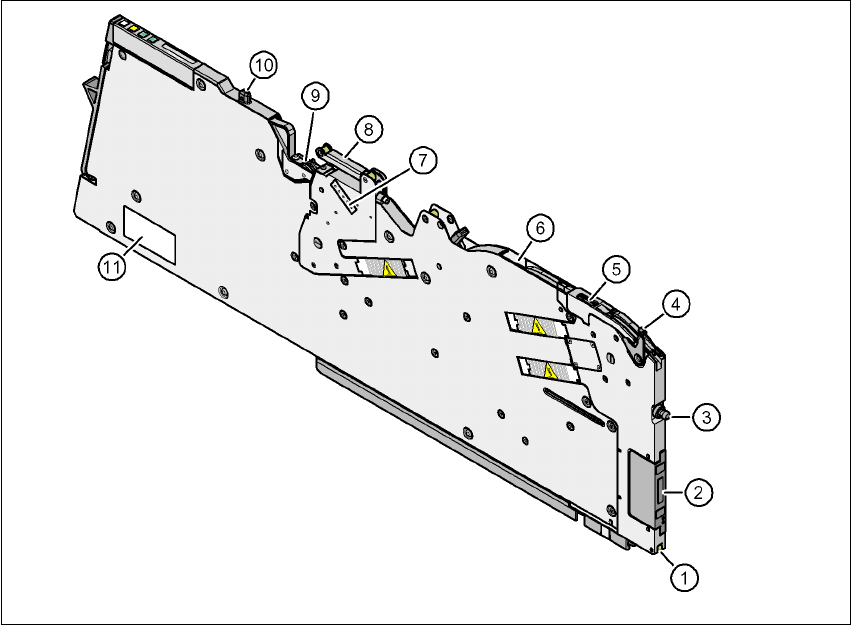
6.1.1.4 Design of the tape feeder module for the SIPLACE X-series
The two following diagrams show the design of the tape feeder module for the X-series with ref-
erence to the 8 mm X tape feeder module.
6
Fig. 6.1 - 1 8 mm X tape feeder module - front view
(1) Locking roller (the locking latch of the component table locks the feeder module in its end po-
sition with the locking roller.)
(2) EDIF (energy and data interface)
(3) "Front" centering pin
(4) Lever for raising the pick-up window in order to thread in and remove the component tape
(5) Pick-up window
(6) Exit from the tape guide channel
(7) Setting the cover foil tension
(8) Cover foil rocker
(9) Cover foil packing wheels
(10) "Back" centering pin
(11) Rating plate
6 Component handling User manual SIPLACE X-Series
6.1 X feeder modules for the component trolley from the SIPLACE X-series Software Version SR.601.xx 11/2005 US Edition
290
6
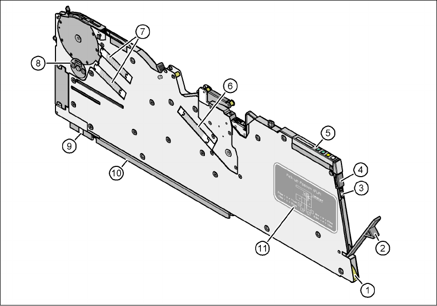
Fig. 6.1 - 2 8 mm X tape feeder module - back view
(1) Entry to the tape guide channel with tape spring
(2) Flap on the cover foil container
(3) Integrated blade for cutting off the cover foil
(4) Removal handle, engaged
(5) Operator panel
(6) Drive motor for the cover foil packing device
(7) Drive motors for the tape conveyor
(8) Rotary valve for removing components
(9) Front slider guide
(10) Back slider guide
(11) Graphical representation of the pick-up position in relation to the component size