X3_X4_Series machine - 第292页
6 Component handling User manual SIPLACE X-Series 6.1 X feeder modules for the c omponent trolley fro m the SIPLACE X-series Software Version SR. 601.xx 11/2005 US Edition 292 6 Fig. 6.1 - 4 Operator panel of the X feede…
User manual SIPLACE X-Series 6 Component handling
Software Version SR.601.xx 11/2005 US Edition 6.1 X feeder modules for the component trolley from the SIPLACE X-series
291
6
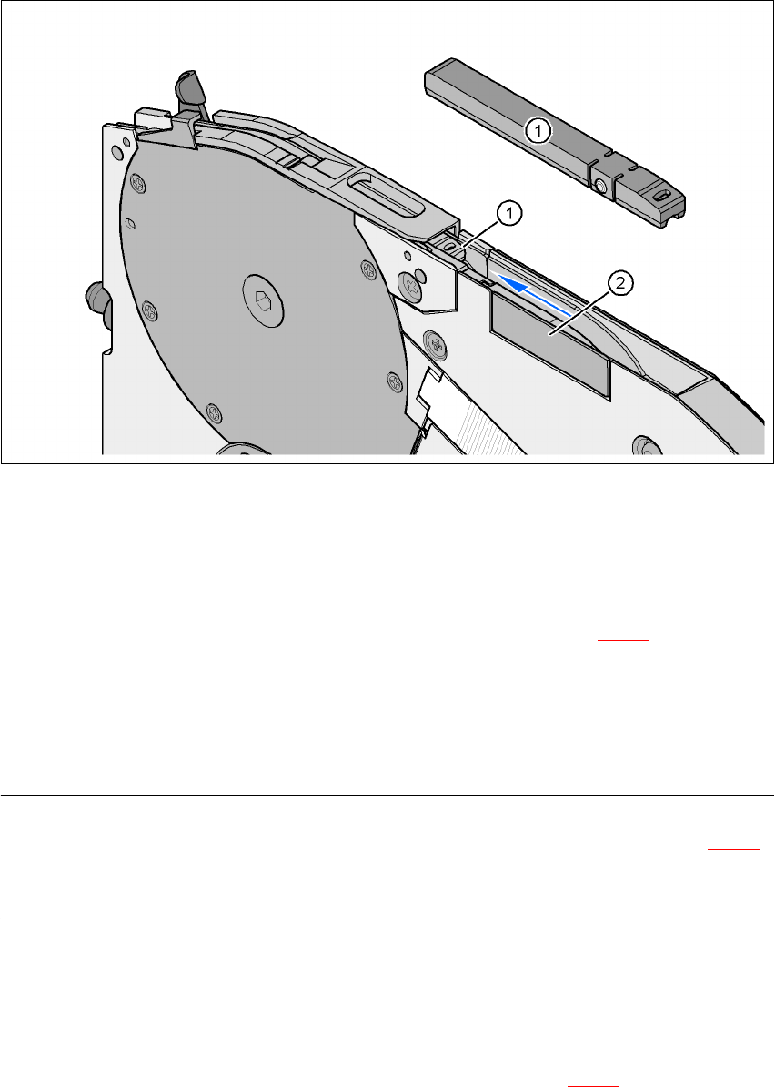
Fig. 6.1 - 3 8 mm X feeder module - tape support and splice sensor
(1) Tape support, removable
(2) Splice sensor installation location
The 8 mm X feeder module is equipped with a tape support (item 1 in Fig. 6.1 - 3
). It can easily
be removed if necessary.
Æ Insert the tang of a watchmaker's screwdriver into the oval opening in the tape support and
pull the tape support out against the direction of travel of the tape.
Æ When you insert the tape support, make sure that it engages in its desired position.
PLEASE NOTE 6
For all components size 0402 and smaller, always insert the tape support (item 1 in Fig. 6.1 - 3
)
into the 8 mm X feeder module. This will give you a constant Z pick up height and will minimize
the time needed to correct the pick up heights.
Splice sensors can be retrofitted to the X tape feeder modules. There are two versions of the sen-
sor:
Splice sensor for 8 mm and 12 mm X tape feeder modules
Splice sensor for 16 mm to 88 mm X tape feeder modules 6
The splice sensor is installed at the position indicated by item 2 in Fig. 6.1 - 3
.
6 Component handling User manual SIPLACE X-Series
6.1 X feeder modules for the component trolley from the SIPLACE X-series Software Version SR.601.xx 11/2005 US Edition
292
6
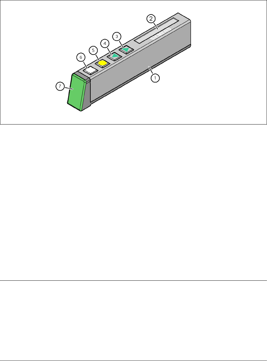
Fig. 6.1 - 4 Operator panel of the X feeder module
(1) Operator panel of the X feeder module
(2) LCD display
In the basic setting, the track number and conveyor increment are displayed.
(3) "FORWARD" button
(4) "BACK" button
(5) "FOIL" button
(6) "SET" button
(7) Multicolor status display
green → Standby
orange → Warning
red → Error
off → Feeder module not contained in the set-up
6
PLEASE NOTE 6
The machine controller switches off the status display of any feeder modules not included in the
set-up. The "LED off" status only occurs when the programming system has preset a job on the
line. This takes some of the work away from the operator since he only has to watch those feeder
modules that are contained in the set-up.
For the actual set-up process - no set-up information at the station, no job sent from SIPLACE
Pro to the station/line - the LED on each feeder module is activated after the set-up has been
made. The operator is thus informed whether everything is OK.
6
User manual SIPLACE X-Series 6 Component handling
Software Version SR.601.xx 11/2005 US Edition 6.1 X feeder modules for the component trolley from the SIPLACE X-series
293
6.1.2 Technical data for the SIPLACE X-series feeder modules
The following pages contain pictures of the X-series feeder modules and the technical data.
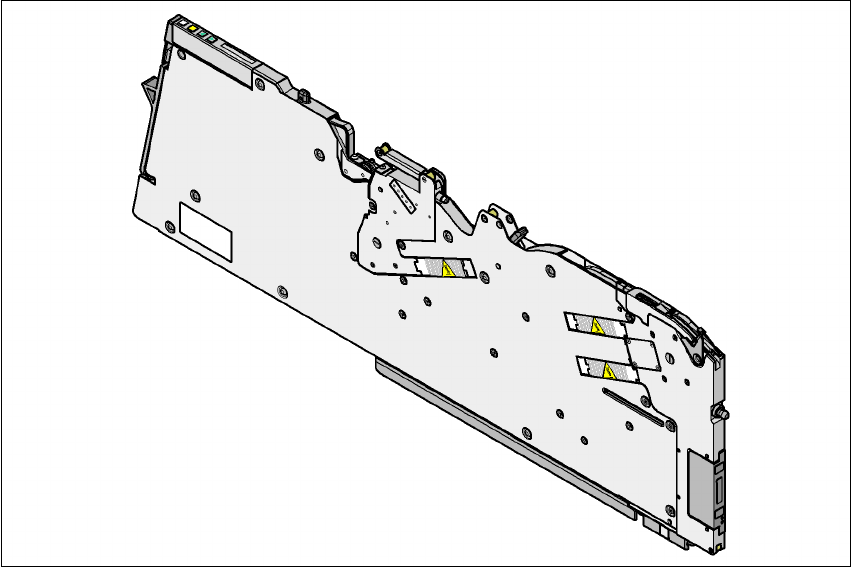
6.1.2.1 8 mm X tape feeder module
6
Fig. 6.1 - 5 8 mm X tape feeder module
6
8 mm X tape feeder module Item no. 00141270-xx
8 mm X tape feeder module with splice sensor Item no. 00141290-xx
Width 10.8 mm
Feeder module locations filled 1
Conveyor increment 1 mm / 2 mm / 4 mm / 8 mm
Changeover time for the component tape < 45 s
Changeover time for the pre-set feeder module
on the machine
< 15 s