X3_X4_Series machine - 第305页
User manual SIPLAC E X-Series 6 Component han dling Software Vers ion SR.601.xx 11/2005 US Edition 6.2 SIPLAC E X-series c omponent trolley 305 6.2 SIP LACE X-ser ies comp onent trolley Up to four SIPLACE X-series compon…
6 Component handling User manual SIPLACE X-Series
6.1 X feeder modules for the component trolley from the SIPLACE X-series Software Version SR.601.xx 11/2005 US Edition
304
WARNING 6
All locations must be equipped with feeder modules in order to guarantee operational reliability. If
there are not enough feeder modules available, unassigned locations should be fitted with a
hand guard (dummy feeder module). When a waffle-pack tray is set up, the remaining locations
have to be protected again with a hand guard.
6
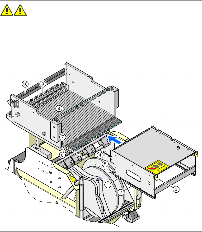
Fig. 6.1 - 15 Inserting a waffle-pack tray holder for the component trolley from the SIPLACE X-series
(1) Front slider guide (6) Insertion aid
(2) Back slider guide (7) Slide bar (omega profile)
(3) "Back" centering pin (8) Recess in the centering bar for holding the
"back" centering pin
(4) "Front" centering pin (9) Locking latches
(5) Locking roller (10) Centering holes on the component table for
holding the "front" centering pin
User manual SIPLACE X-Series 6 Component handling
Software Version SR.601.xx 11/2005 US Edition 6.2 SIPLACE X-series component trolley
305
6.2 SIPLACE X-series component trolley
Up to four SIPLACE X-series component trolleys can be docked into the machines from the
SIPLACE X-series. The locations are numbered as shown in the diagram below.
6
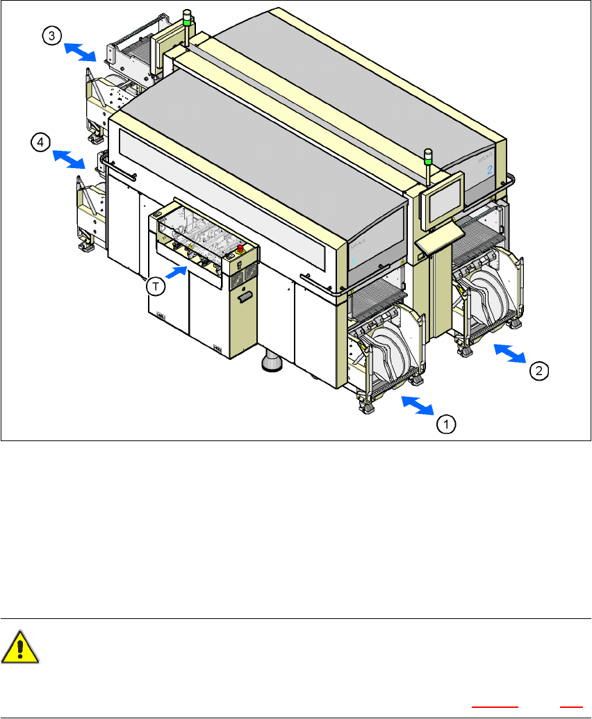
Fig. 6.2 - 1 Component trolley locations, SIPLACE X-series
(1) Location 1
(2) Location 2
(3) Location 3
(4) Location 4
(T) PCB direction of travel
CAUTION 6
The component trolleys from the SIPLACE X-series may only be docked into locations at which
the component trolley docking unit for the SIPLACE X-series is installed (Fig. 5.10 - 3, page 278).
6 Component handling User manual SIPLACE X-Series
6.2 SIPLACE X-series component trolley Software Version SR.601.xx 11/2005 US Edition
306
The component changeover tables are stand-alone modules that can be set up with feeders at an
external set-up area. This means that the production process only has to be interrupted briefly in
order to change the component trolley.
6
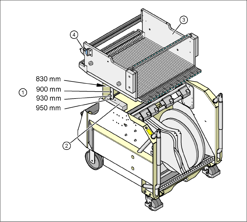
Fig. 6.2 - 2 Component trolley, SIPLACE X-series with a PCB conveyor height of 950 mm
6
(1) Holes for the PCB conveyor heights 900, 930 and 950 mm in the guide columns. For the
830 mm conveyor height, the component table lies on the block (2).
(2) Supporting block
(3) Component feeder table
(4) Contact for switching the safety switch in the component trolley docking unit