X3_X4_Series machine - 第311页
User manual SIPLAC E X-Series 6 Component han dling Software Vers ion SR.601.xx 11/2005 US Edition 6.2 SIPLAC E X-series c omponent trolley 311 6.2.5 SIPLACE X - seri es component t able The front s lider gui des of the …
6 Component handling User manual SIPLACE X-Series
6.2 SIPLACE X-series component trolley Software Version SR.601.xx 11/2005 US Edition
310
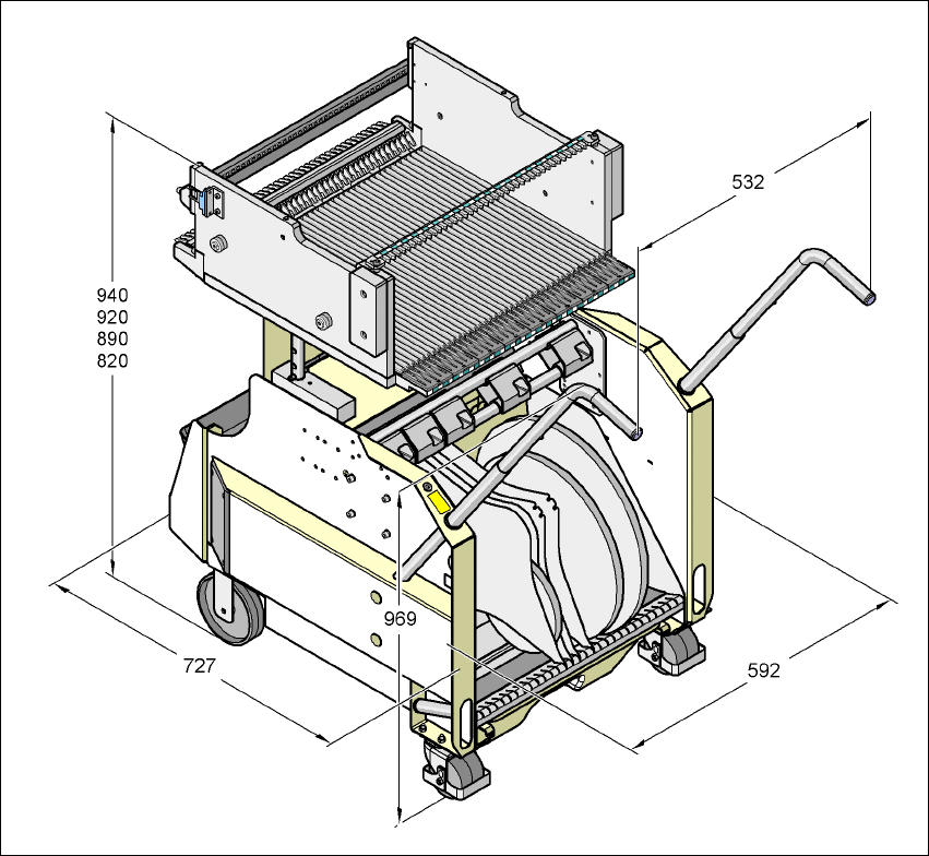
6.2.4 Dimensions of the component trolley, SIPLACE X-series
6
Fig. 6.2 - 5 Dimensions of the component trolley, SIPLACE X-series, all dimensions in
User manual SIPLACE X-Series 6 Component handling
Software Version SR.601.xx 11/2005 US Edition 6.2 SIPLACE X-series component trolley
311
6.2.5 SIPLACE X-series component table
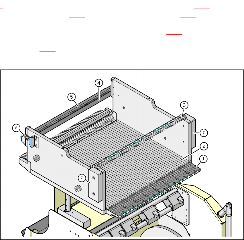
The front slider guides of the feeder modules are placed on the insertion aid (item 1 in Fig. 6.2 -
6). As it is pushed in, the guides of the feeder module (item 12 and 13 in Fig. 6.1 - 2) slide on the
guide profile (item 2 in Fig. 6.2 - 6
) as far as the stop bar (item 4 in Fig. 6.2 - 6). A centering hole
(item 5 in Fig. 6.2 - 6
) on the stop bar holds the "front" centering pin (item 4 in Fig. 6.1 - 1) of the
X feeder module. At the same time, the locking latch (item 1 in Fig. 6.2 - 7
) of the component table
latches on the locking roller (item 1 in Fig. 6.1 - 1
) of the feeder module. The "back" centering pin
(item 12 in Fig. 6.1 - 1
) on the top of the feeder module is held by the recess in the centering bar
(item 3 in Fig. 6.2 - 6
).
6
Fig. 6.2 - 6 Component table, SIPLACE X-series, back view
(1) Insertion aid
(2) Guide profile (Ω profile)
(3) Centering bar for holding the "back" centering pin for X feeder modules
(4) Stop bar
(5) Centering holes
(6) Contact for switching the safety switch of the emergency stop circuit
(7) Hand guard
6 Component handling User manual SIPLACE X-Series
6.2 SIPLACE X-series component trolley Software Version SR.601.xx 11/2005 US Edition
312
6
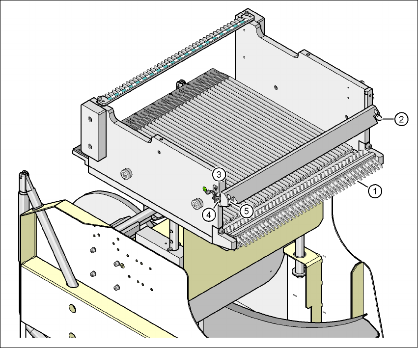
Fig. 6.2 - 7 Component table, SIPLACE X-series, front view
(1) Locking latches
(2) Centering pin on the component table
(3) Compressed air coupling
(4) Grounding pin
(5) Centering hole on the component table