X3_X4_Series machine - 第318页
6 Component handling User manual SIPLACE X-Series 6.4 Used tape c hannel - CO trolley docking unit, SIPLACE X -series Software Version SR.601.xx 11/2005 US E dition 318 6.4.2 Removing the sep arating plate for t ape pock…
User manual SIPLACE X-Series 6 Component handling
Software Version SR.601.xx 11/2005 US Edition 6.4 Used tape channel - CO trolley docking unit, SIPLACE X-series
317
6.4 Used tape channel - CO trolley docking unit,
SIPLACE X-series
6.4.1 Separating plate for tape pocket heights up to 12 mm
In the standard version, the used tape channel can guide component tapes with a maximum
pocket height of 12 mm to the pneumatic tape cutter.
6
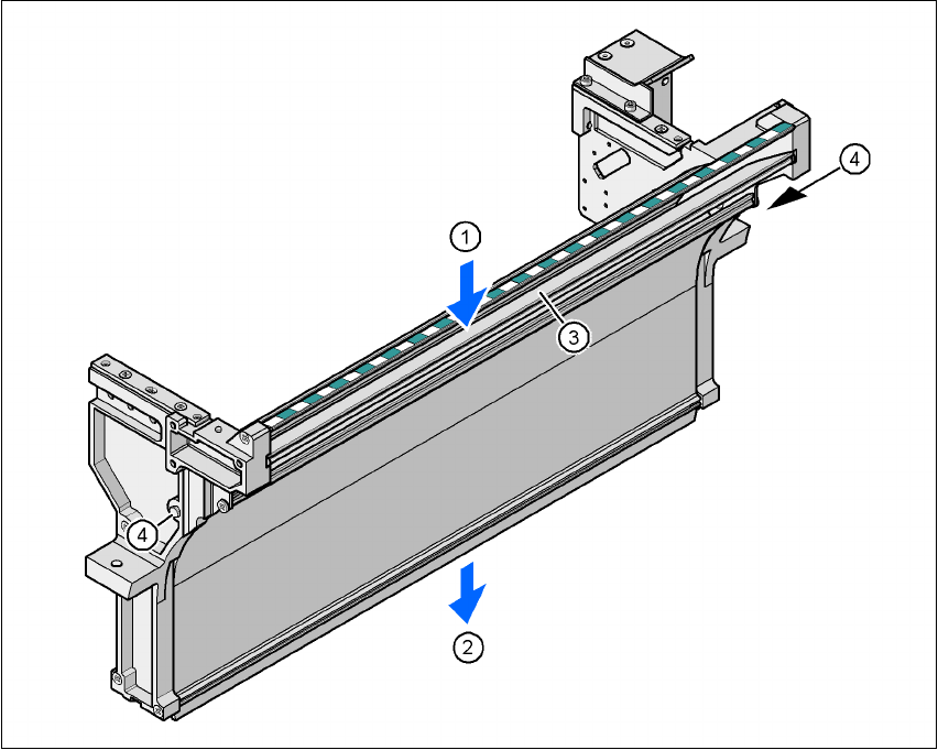
Fig. 6.4 - 1 Used tape chute, SIPLACE X-series
(1) Inlet slot for the used tapes
(2) Outlet slot for the used tape above the pneumatic tape cutter
(3) Dividing plate for tapes < 12 mm (can be removed for tapes > 12 mm)
(4) DIN 93384 screw - M4x20, 2x
6 Component handling User manual SIPLACE X-Series
6.4 Used tape channel - CO trolley docking unit, SIPLACE X-series Software Version SR.601.xx 11/2005 US Edition
318
6.4.2 Removing the separating plate for tape pocket heights > 12 mm
If X feeder modules are used, the component tapes work with a pocket height > 12 mm, so the
separating plate (item 3 in Fig. 6.4 - 1
) must be removed.
WARNING 6
Æ Switch the placement machine off at the main switch to remove the dividing plate.
Æ Disconnect the machine from the power and compressed air supply.
Æ Secure the machine to prevent it being switched on again, as described in section 2.10, page
86
.
Æ Wait until the operating pressure for the tape cutter has dropped to 0 MPa.
Æ Do not reach inside the used tape channel.
Æ Loosen the two hexagon head screws (item 4 in Fig. 6.4 - 1).
Æ Pull out the dividing plate.
PLEASE NOTE
Do not position feeder modules with shallow pockets immediately beside bar feeder modules
with deep pockets. The used tapes could overlap and build up.
6
User manual SIPLACE X-Series 6 Component handling
Software Version SR.601.xx 11/2005 US Edition 6.5 Docking station for the component trolley from the SIPLACE X-series
319
6.5 Docking station for the component trolley from the
SIPLACE X-series
Item no. 00116933-xx
6.5.1 Overview
The docking station is an additional component the set-up area. It forms the link between the set-
up area and the component trolley for the SIPLACE X-series. The docking station allows the com-
ponent trolleys to be set up with feeder modules and function tests and set-up checks to be carried
out externally.
6
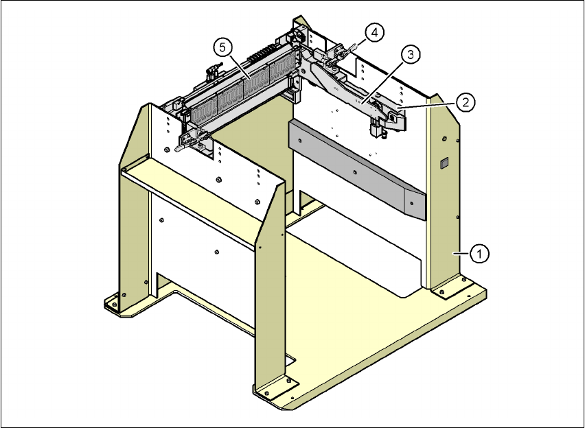
Fig. 6.5 - 1 Docking station, SIPLACE X-series
(1) Docking station
(2) Component trolley docking unit, X-series
(3) Rails for guiding and docking in the component table
(4) Horizontal tensioner for locking the component trolley
(5) EDIF (energy and data interface)