X3_X4_Series machine - 第326页
6 Component handling User manual SIPLACE X-Series 6.5 Docking station for the component tr olley from the SIPLA CE X-series Sof tware Version SR. 601.xx 11/2005 US Edition 326 6.5.6 St arting up the docking st ation 6.5.…
User manual SIPLACE X-Series 6 Component handling
Software Version SR.601.xx 11/2005 US Edition 6.5 Docking station for the component trolley from the SIPLACE X-series
325
6.5.5 Controls and displays
6
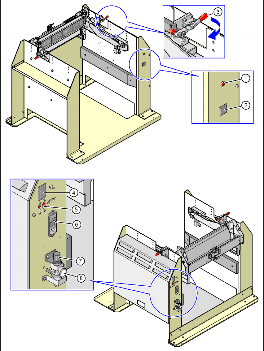
Fig. 6.5 - 4 Docking station - Controls and displays
6 Component handling User manual SIPLACE X-Series
6.5 Docking station for the component trolley from the SIPLACE X-series Software Version SR.601.xx 11/2005 US Edition
326
6.5.6 Starting up the docking station
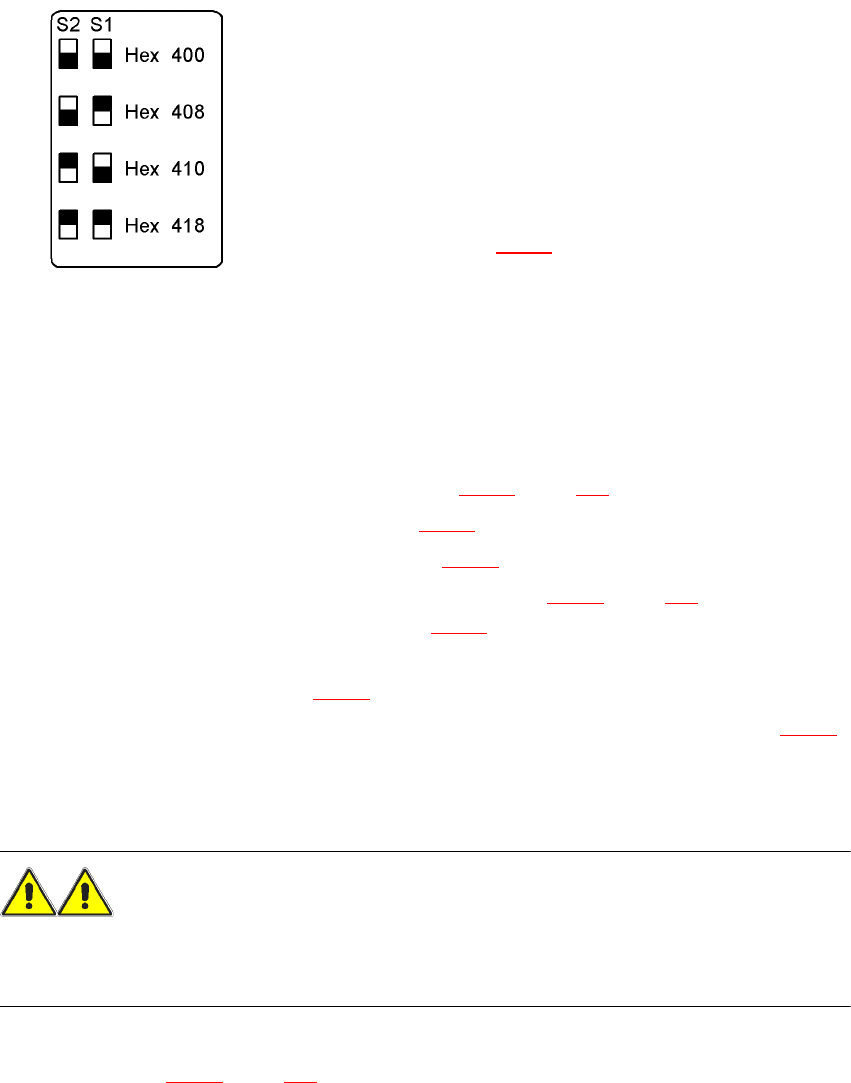
6.5.6.1 Setting the CAN bus address
6
Fig. 6.5 - 5 Docking station, addresses
6
6
6.5.6.2 Switching on the docking station
Æ Connect the compressed air line (item 1 in Fig. 6.5 - 2, page 321).
Æ Connect the CAN bus cable (item 2 in Fig. 6.5 - 2).
Æ Connect the main power cable (item 3 in Fig. 6.5 - 2).
Æ Switch the docking station on at the switch (item 6 in Fig. 6.5 - 4, page 325).
The red power indicator lamp (item 1 in Fig. 6.5 - 4
) should light up.
Æ Check the operating pressure.
The manometer (item 8 in Fig. 6.5 - 4
) should read around 0.5 MPa (5 bar).
Æ If necessary, adjust the operating pressure by turning the rotary knob (item 7 in Fig. 6.5 - 4).
6.5.7 Docking the SIPLACE X-series component trolley into the docking station
WARNING 6
Æ Only component trolleys from the SIPLACE X-series may be operated at this docking station.
Æ While docking, do not reach into the areas between component trolley and docking station.
Æ Release the two horizontal tensioners by moving them in the direction indicated by the arrow
(item 3 in Fig. 6.5 - 4
, page 325).
Up to 4 docking stations can be connected to the PC via a CAN
bus cable.
– Make sure that you do not assign CAN bus
addresses to docking stations connected to one
another more than once.
– For each docking station, set the address using
switches S1 and S2
(item 5 in Fig. 6.5 - 4
) as shown opposite.
User manual SIPLACE X-Series 6 Component handling
Software Version SR.601.xx 11/2005 US Edition 6.5 Docking station for the component trolley from the SIPLACE X-series
327
Æ Push the component trolley carefully into the docking station.This will raise the component
table.
Æ Make sure that the component trolley is standing fully on the base plate of the docking station.
Æ Apply the two horizontal tensioners (item 3 in Fig. 6.5 - 4, page 325.
The component table is raised into its definitive position and locked.
Æ Use the button (item 2 in Fig. 6.5 - 4) to lock or release all the feeder modules on the compo-
nent table.
6.5.8 Undocking the SIPLACE X-series component trolley from the docking sta-
tion
WARNING 6
Æ While undocking, do not reach into the areas between component trolley and docking station.
Æ Release the two horizontal tensioners (item 3 in Fig. 6.5 - 4, page 325).
The component table is lowered.
Æ Now pull the component trolley out of the docking station.