X3_X4_Series machine - 第327页
User manual SIPLAC E X-Series 6 Component han dling Software Version SR.601.xx 11/2005 US Edition 6.5 Docking station for the component trolley from the SIPLACE X-series 327 Æ Push the c omponent tr olley carefull y into…
6 Component handling User manual SIPLACE X-Series
6.5 Docking station for the component trolley from the SIPLACE X-series Software Version SR.601.xx 11/2005 US Edition
326
6.5.6 Starting up the docking station
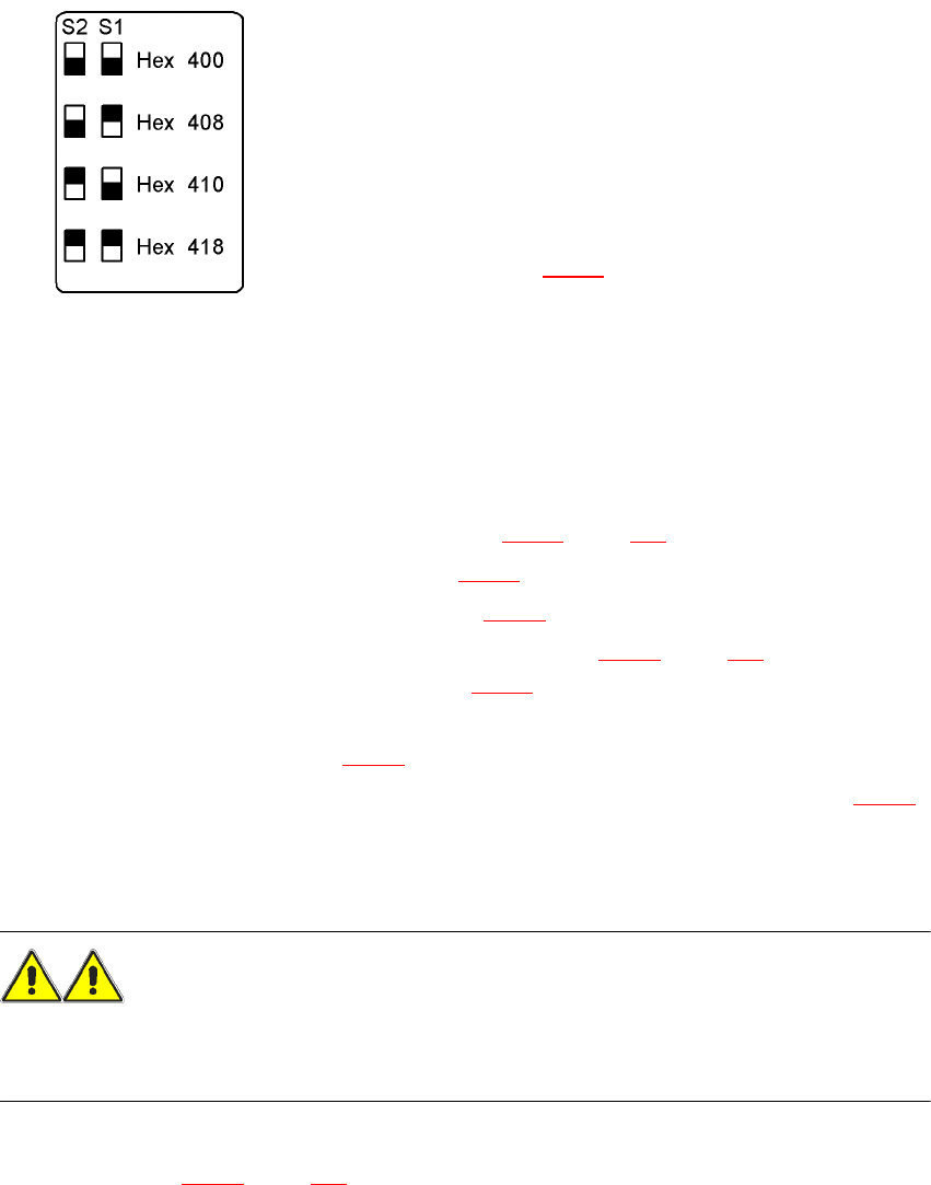
6.5.6.1 Setting the CAN bus address
6
Fig. 6.5 - 5 Docking station, addresses
6
6
6.5.6.2 Switching on the docking station
Æ Connect the compressed air line (item 1 in Fig. 6.5 - 2, page 321).
Æ Connect the CAN bus cable (item 2 in Fig. 6.5 - 2).
Æ Connect the main power cable (item 3 in Fig. 6.5 - 2).
Æ Switch the docking station on at the switch (item 6 in Fig. 6.5 - 4, page 325).
The red power indicator lamp (item 1 in Fig. 6.5 - 4
) should light up.
Æ Check the operating pressure.
The manometer (item 8 in Fig. 6.5 - 4
) should read around 0.5 MPa (5 bar).
Æ If necessary, adjust the operating pressure by turning the rotary knob (item 7 in Fig. 6.5 - 4).
6.5.7 Docking the SIPLACE X-series component trolley into the docking station
WARNING 6
Æ Only component trolleys from the SIPLACE X-series may be operated at this docking station.
Æ While docking, do not reach into the areas between component trolley and docking station.
Æ Release the two horizontal tensioners by moving them in the direction indicated by the arrow
(item 3 in Fig. 6.5 - 4
, page 325).
Up to 4 docking stations can be connected to the PC via a CAN
bus cable.
– Make sure that you do not assign CAN bus
addresses to docking stations connected to one
another more than once.
– For each docking station, set the address using
switches S1 and S2
(item 5 in Fig. 6.5 - 4
) as shown opposite.
User manual SIPLACE X-Series 6 Component handling
Software Version SR.601.xx 11/2005 US Edition 6.5 Docking station for the component trolley from the SIPLACE X-series
327
Æ Push the component trolley carefully into the docking station.This will raise the component
table.
Æ Make sure that the component trolley is standing fully on the base plate of the docking station.
Æ Apply the two horizontal tensioners (item 3 in Fig. 6.5 - 4, page 325.
The component table is raised into its definitive position and locked.
Æ Use the button (item 2 in Fig. 6.5 - 4) to lock or release all the feeder modules on the compo-
nent table.
6.5.8 Undocking the SIPLACE X-series component trolley from the docking sta-
tion
WARNING 6
Æ While undocking, do not reach into the areas between component trolley and docking station.
Æ Release the two horizontal tensioners (item 3 in Fig. 6.5 - 4, page 325).
The component table is lowered.
Æ Now pull the component trolley out of the docking station.

6 Component handling User manual SIPLACE X-Series
6.6 S feeder modules for the SIPLACE HF component trolley Software Version SR.601.xx 11/2005 US Edition
328
6.6 S feeder modules for the SIPLACE HF component
trolley
The following feeder modules are currently available to provide the placement machine with the
various component types:
Tape feeder modules 6
– 8 mm SII feeder module
– 3 x 8 mm S feeder module, 3 x 8 mm S feeder module for 0201/0402 components
– 12 mm S feeder module for powdered metal-based capacitors, C/D model
– 12 mm S feeder module for powdered metal-based capacitors, E model
– S feeder module for 12/16 mm, 24/32 mm, 44 mm, 56 mm, 72 mm and 88 mm
– S DP feeder module for deep pockets, 24/32 mm, 44 mm and 56 mm
Other feeder modules 6
– Linear vibratory feeder, type 3
– Bulk case feeder module
– Surf tape feeder module for 8 mm, 12 mm and 16 mm
These feeder modules can be used to process all components with the most common package
forms, such as bulk cases, stick magazines and taped components.
The most important feature of the modular component feeding system is its great flexibility. For
example, the feeding rate can be set on the feeder module. Paper and blister tapes can be pro-
cessed with the tape feeder modules. A small range of feeder module types is sufficient to place
a large range of component types.
The position detection system on the feeder modules can precisely determine the component
pick-up position. The position detection is carried out automatically whenever the feeder module
or component trolley is changed.
The feeder modules can be quickly and easily changed or replaced, even by unskilled personnel.
PLEASE NOTE
Detailed information on the feeder modules can be found in the operating instructions for compo-
nent feeder modules.