X3_X4_Series machine - 第349页
User manual SIPLAC E X-Series 6 Component han dling Software Version SR.601.xx 11/2005 US Edition 6.6 S feeder modules for the SIPLACE HF component trolley 349 The amoun t of flux requ ired for the process i s reduce d t…
6 Component handling User manual SIPLACE X-Series
6.6 S feeder modules for the SIPLACE HF component trolley Software Version SR.601.xx 11/2005 US Edition
348
6.6.3.2 Changing the retainer
Æ Hold the retainer (G in Fig. 6.6 - 16) firmly. Press the thrust pad downwards (F in Fig. 6.6 - 16)
and remove the retainer by pressing it out sideways.
6.6.3.3 Data entry
Define the waffle-pack trays as described in the SIPLACE Pro operating instructions. 6
6.6.4 Dip module for the SIPLACE HF component trolley
6
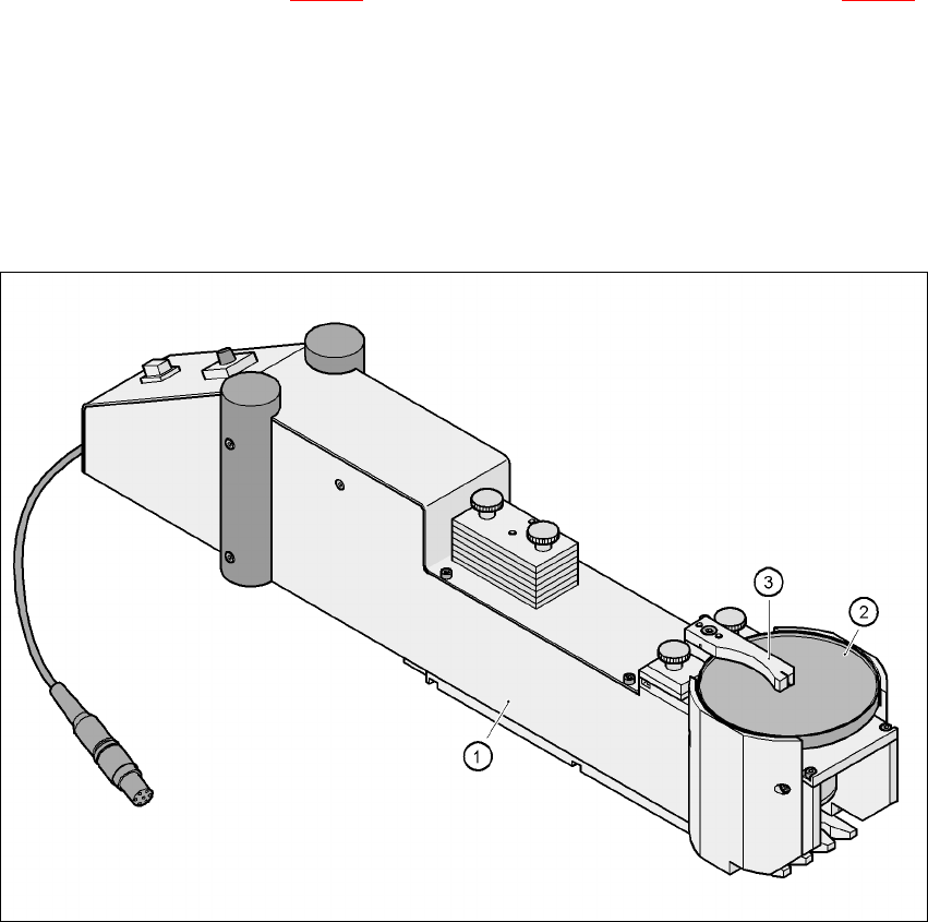
Fig. 6.6 - 17 Dip module
(1) Dip module
(2) Rotating plate
(3) Squeegee
6.6.4.1 Principle of dip fluxing
The dip module (item 1) is used to wet flip-chip and CSP components with flux or conductive ad-
hesive. The flux holder is a rotating plate (item 2) on which a thin film of flux (e.g. 40 µm) is created
with a squeegee (item 3). This method is particularly suitable for highly viscous (honey-like) fluxes.
User manual SIPLACE X-Series 6 Component handling
Software Version SR.601.xx 11/2005 US Edition 6.6 S feeder modules for the SIPLACE HF component trolley
349
The amount of flux required for the process is reduced to a minimum coating thickness since only
the undersides of the bumps have to be wetted.
The Dip module is suitable for the following placement heads:
6-segment Collect & Place head
12-segment Collect & Place head
TwinHead 6
The Dip module is regarded as a separate feeder module type by the set-up optimization. There
is no limit to the number of dip modules at the individual locations.
6.6.4.2 Technical data
Item no. 00117010-xx 6
Feeder module locations filled 3 6
Component size max. 36 x 36 mm²
depending on the placement head type 6
Possible coating thicknesses 25, 35, 45, 55, 65, 75 µm 6
Time required to change the coating thickness Less than 1 min. 6
Gap height tolerance ± 5 mm 6
Plate rotating speed Programmable from 0 - 10 sec.
in 0.1 sec. increments 6
Component dip time Programmable from 0 - 2 sec.
in 0.1 sec. increments 6
Flux Highly viscous flux, conductive adhesive 6
6
6 Component handling User manual SIPLACE X-Series
6.7 SIPLACE HF component trolleys Software Version SR.601.xx 11/2005 US Edition
350
6.7 SIPLACE HF component trolleys
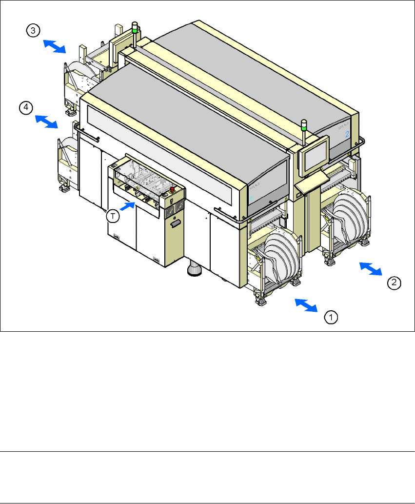
Up to four SIPLACE HF component trolleys can be docked into the machines from the SIPLACE
X-series. The locations are numbered as shown in the diagram below.
6
Fig. 6.7 - 1 Component trolley locations, SIPLACE HF
(1) Location 1
(2) Location 2
(3) Location 3
(4) Location 4
(T) PCB direction of travel
PLEASE NOTE 6
The SIPLACE HF component trolley cannot be used together with the 20-segment Collect &
Place head.