X3_X4_Series machine - 第359页
User manual SIPLAC E X-Series 6 Component han dling Software Vers ion SR.601.xx 11/2005 US Edition 6.7 SIPLACE HF component trolleys 359 6.7.7 Mount for the middle t a pe reel on 3x8 mm S feeder modules T ype 3x8 mm S fe…
6 Component handling User manual SIPLACE X-Series
6.7 SIPLACE HF component trolleys Software Version SR.601.xx 11/2005 US Edition
358
6
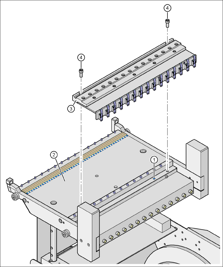
Fig. 6.7 - 6 Compressed air supply for bulk case feeder modules, SIPLACE HF component trolley
6
(1) Sealing plug on the component feeder table
(2) Component feeder table
(3) Compressed air supply for bulk case feeder modules
(4) Screw DIN 912, M8x20
(5) Retaining clamp
User manual SIPLACE X-Series 6 Component handling
Software Version SR.601.xx 11/2005 US Edition 6.7 SIPLACE HF component trolleys
359
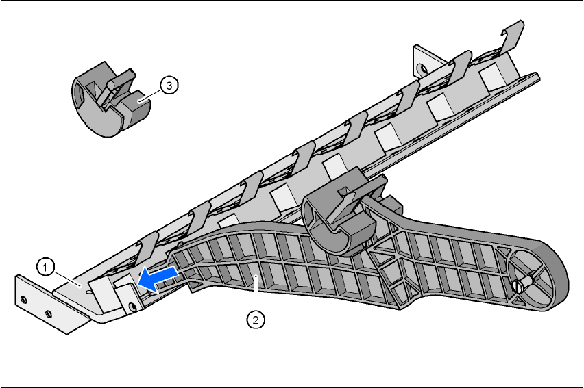
6.7.7 Mount for the middle tape reel on 3x8 mm S feeder modules
Type 3x8 mm S feeder modules transport components to the pick-up position on three feeder
tracks. The tape reels of the two outer tracks are positioned between the separating plates in the
tape container. The middle tape reel is arranged over the tape reels for the two outer tracks.
For the middle tape reels you will therefore also need:
– 1 adapter plate for holding the tape reel holder (item 1),
– for every two feeder modules, 1 tape reel holder (item 2) and
– 1 shortened idler pulley (item 3) for the tape reel holder at location 1 of the component feeder
table.
The adapter plate is fixed inside the component trolley with four fillister head screws, and the tape
reel holders are inserted into the square openings in the adapter plate.
6
Fig. 6.7 - 7 Mount for the middle tape reel on 3x8 mm S feeder modules
(1) Adapter plate
(2) Tape reel holder
(3) Idler pulley, shortened
6 Component handling User manual SIPLACE X-Series
6.7 SIPLACE HF component trolleys Software Version SR.601.xx 11/2005 US Edition
360
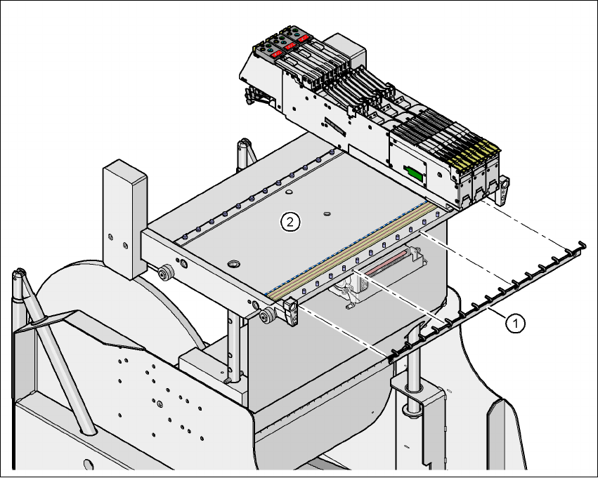
6.7.8 Feeder module fixing, SIPLACE HF component trolleys
The feeder module fixing is an additional mechanical locking device. It prevents the feeder mod-
ules accidentally moving on the component table and thus prevents the risk of collision with the
placement head.
The feeder module fixing is fixed to the front panel of the component table using screws. The claws
fix the feeder module feet. One feeder module fixing is needed for each component trolley.
6
Fig. 6.7 - 8 Feeder module fixing, SIPLACE HF component trolleys
(1) Feeder module fixing
(2) Component feeder table