X3_X4_Series machine - 第361页
User manual SIPLAC E X-Series 6 Component han dling Software Vers ion SR.601.xx 11/ 2005 US Ed ition 6.8 Used tape c hute, SIPLACE H F 361 6.8 Used t ape chute, SIPLACE HF 6 Fig. 6.8 - 1 Used tape chute f or SIPLACE HF P…
6 Component handling User manual SIPLACE X-Series
6.7 SIPLACE HF component trolleys Software Version SR.601.xx 11/2005 US Edition
360
6.7.8 Feeder module fixing, SIPLACE HF component trolleys
The feeder module fixing is an additional mechanical locking device. It prevents the feeder mod-
ules accidentally moving on the component table and thus prevents the risk of collision with the
placement head.
The feeder module fixing is fixed to the front panel of the component table using screws. The claws
fix the feeder module feet. One feeder module fixing is needed for each component trolley.
6
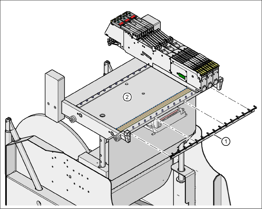
Fig. 6.7 - 8 Feeder module fixing, SIPLACE HF component trolleys
(1) Feeder module fixing
(2) Component feeder table
User manual SIPLACE X-Series 6 Component handling
Software Version SR.601.xx 11/2005 US Edition 6.8 Used tape chute, SIPLACE HF
361
6.8 Used tape chute, SIPLACE HF
6
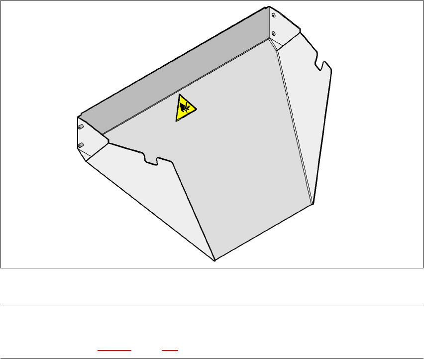
Fig. 6.8 - 1 Used tape chute for SIPLACE HF
PLEASE NOTE 6
The SIPLACE HF used tape chute can only be installed on the SIPLACE HF component trolley
docking unit (see Fig. 5.10 - 6, page 281.
6 Component handling User manual SIPLACE X-Series
6.9 Used tape channel - component trolley docking unit SIPLACE HF Software Version SR.601.xx 11/2005 US Edition
362
6.9 Used tape channel - component trolley docking
unit SIPLACE HF
6.9.1 Separating plate for tape pocket heights up to 17 mm
In the standard version, the used tape channel can guide component tapes with a maximum
pocket height of 17 mm to the pneumatic tape cutter.
6
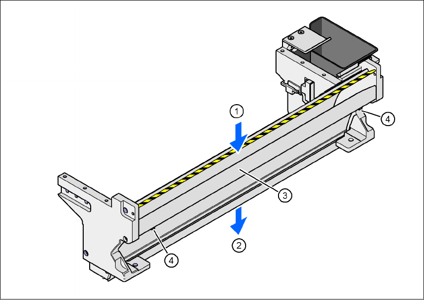
Fig. 6.9 - 1 Used tape channel, SIPLACE HF
(1) Inlet slot for the used tapes
(2) Outlet slot for the used tape above the pneumatic tape cutter
(3) Dividing plate for tapes < 17 mm (can be removed for tapes > 17 mm)
(4) DIN 84 - M3x6 screw, 2x