X3_X4_Series machine - 第365页
User manual SIPLAC E X-Series 6 Component han dling Software Version SR.601.xx 11/2005 US Edition 6.10 Matrix tray changer 365 6 Fig. 6.10 - 1 Matrix tray changer 2, bac k view (1) Ma in power switch (2) Emer gency stop …
6 Component handling User manual SIPLACE X-Series
6.10 Matrix tray changer Software Version SR.601.xx 11/2005 US Edition
364
6.10 Matrix tray changer
The use of flatpack ICs is becoming an increasingly significant aspect in the production of flat
modules. These components are now almost exclusively provided in waffle trays. The space re-
quired by waffle trays is relatively large in comparison to the component density, however. The low
component capacity also requires the waffle trays to be changed frequently, which means that the
placement sequence has to be interrupted if the trays are changed manually.
The use of a matrix tray changer eliminates this unnecessary time loss since the waffle trays are
stored and automatically changed. Programmable, random access to up to 100 x waffle-pack
trays also considerably increases the range of components that can be made available.
6.10.1 Description
The matrix tray changer can be used to store and change up to 100 waffle trays fully automatically.
The levels (storage locations in the towers) for the waffle trays are numbered consecutively in as-
cending order from bottom to top.
The towers move independently of one another in the vertical direction until the selected maga-
zine is within range of the feed axis. The horizontal feed axis transports the waffle-pack tray from
the tower into the access area of the placement head.
Tower 1 has 30 levels, each of which can hold 2 JEDEC trays or one large tray up to 240 x 340
mm² from the waffle-pack tray carriers.
Tower 2 has a capacity of 40 levels for JEDEC trays.
In place of a component trolley, a matrix tray changer may be docked into locations 2 and 4 on the
X2 machine, but only at location 2 on the X3 machine. The docking unit installed for the compo-
nent trolley can be replaced with the docking device for the matrix tray changer. Or conversely,
the matrix tray changer can be replaced with a component trolley.
The matrix tray changer has an integral chassis, and is therefore easy to move to other locations.
It is supplied with the PCB conveyor height implemented for X2/X3 machines, but can be adapted
for the 830, 900, 930 and 950 mm PCB conveyor heights with just a few simple operations.
User manual SIPLACE X-Series 6 Component handling
Software Version SR.601.xx 11/2005 US Edition 6.10 Matrix tray changer
365
6
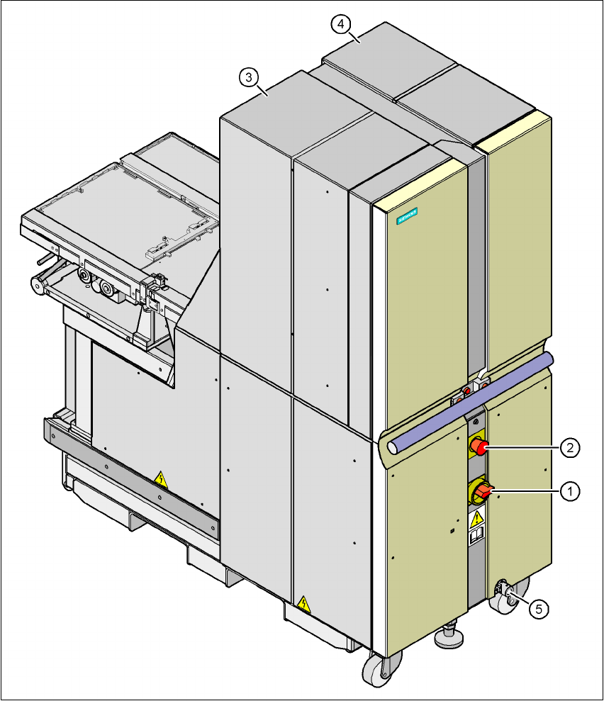
Fig. 6.10 - 1 Matrix tray changer 2, back view
(1) Main power switch
(2) Emergency stop button
(3) Tower 1 for holding up to 30 waffle-pack tray carriers (up to 60 JEDEC trays)
(4) Tower 2 for holding up to 40 waffle-pack tray carriers (up to 40 JEDEC trays)
(5) Point for attaching the crank for adjusting the height of matrix tray changer 2
6 Component handling User manual SIPLACE X-Series
6.10 Matrix tray changer Software Version SR.601.xx 11/2005 US Edition
366
6
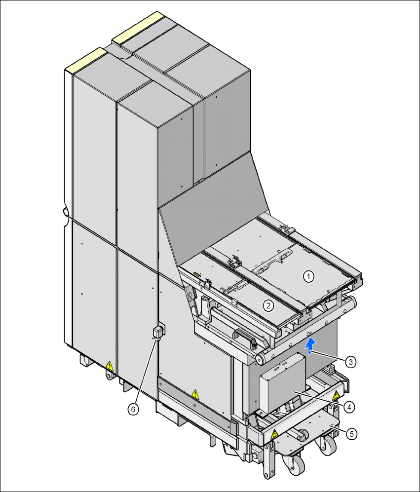
Fig. 6.10 - 2 Matrix tray changer 2, front view
(1) Feed axis 1
(2) Feed axis 2
(3) Interface plug for docking in to the placement machine
(4) Electronic control unit
(5) Integral chassis
(6) Cable gland for the power supply cable