X3_X4_Series machine - 第380页
7 Station extensions User manual SIPLACE X-S eries 7.1 Nozzle changer Software Version S R.601.xx 11/2005 US Edition 380 PLEAS E NOTE 7 – Move the locking pl ate in to the "Mag azine lo cked" p osition. – Befor…
User manual SIPLACE X-Series 7 Station extensions
Software Version SR.601.xx 11/2005 US Edition 7.1 Nozzle changer
379
WARNING 7
Any lever that is protruding over the magazine (item 1 in Fig. 7.1 - 7
) can result in a head crash.
You should therefore make sure that the lever does not protrude over the magazines.
7
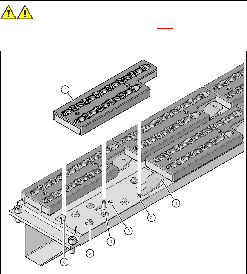
Fig. 7.1 - 7 Changing the magazine
(1) Lever for raising the magazine
(2) Parallel pin, engages in the hole in the magazine
(3) Spring pin for triggering the microswitch
(4) Pin of the slide mechanism, moves the locking plate
(5) Ball of snap fastener
(6) Parallel pin, engages in the slot in the magazine
(7) Locking plate in the "Magazine locked" position
7 Station extensions User manual SIPLACE X-Series
7.1 Nozzle changer Software Version SR.601.xx 11/2005 US Edition
380
PLEASE NOTE 7
– Move the locking plate into the "Magazine locked" position.
– Before inserting, align the magazine so that the centering pins (item 2 and 6 in Fig. 7.1 - 7
)
slide into the centering holes and slot (item 6 in Fig. 7.1 - 6).
Æ Place the magazine on the snap fastener balls (item 5 in Fig. 7.1 - 7).
Æ Press the magazine down evenly so that the snap fastener balls engage in all the snap fas-
teners at the same time.
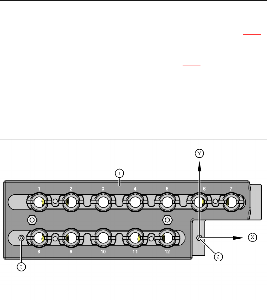
7.1.1.9 Position detection
Each magazine of the nozzle changer has two fiducials: one for determining the position and one
for determining the angular position.
7
Fig. 7.1 - 8 Nozzle magazine - holder numbering, fiducials for determining the position and angular position
(1) Locking plate in the "Magazine open" position
(2) Fiducial for determining the position
(3) Fiducial for determining the angular position
User manual SIPLACE X-Series 7 Station extensions
Software Version SR.601.xx 11/2005 US Edition 7.1 Nozzle changer
381
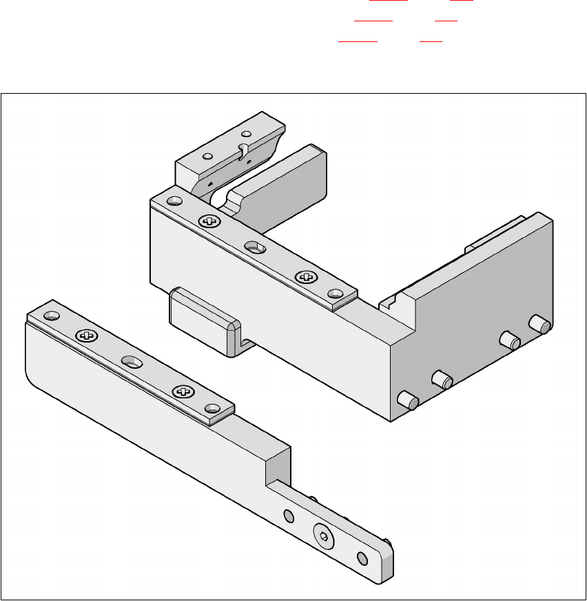
7.1.1.10 "Row 2" nozzle changers for the 20-segment Collect&Place head
Item no. 00119716-xx
The "row 2" nozzle changer may be installed at the following locations:
X4 placement machine: Locations 1, 2, 3 and 4 (see Fig. 7.1 - 2
, page 372)
X3 placement machine: Locations 1, 3 and 4 (see Fig. 7.1 - 3
, page 373)
X2 placement machine: Locations 1 and 3 (see Fig. 7.1 - 4
, page 374)
The retrofit package contains an assembly kit.
7
Fig. 7.1 - 9 Assembly kit for the "row 2" nozzle changer
7
7