X3_X4_Series machine - 第390页
7 Station extensions User manual SIPLACE X-S eries 7.1 Nozzle changer Software Version S R.601.xx 11/2005 US Edition 390 7.1.2.8 Chan ging the magazine Æ T o remo ve the mag azine, push the spring hook (item 1 in Fig. 7.…

User manual SIPLACE X-Series 7 Station extensions
Software Version SR.601.xx 11/2005 US Edition 7.1 Nozzle changer
389
7.1.2.7 Notes on operation
Æ When you fill a magazine with a certain nozzle type for the first time, attach an adhesive label
to identify the type.
PLEASE NOTE 7
Fill the magazines off the machine and always replace complete magazines. 7
Æ Open the locking plate and place the nozzles in the nozzle holders.
Æ Close the locking plate so that the nozzles cannot drop out of the magazines.
CAUTION 7
Before you fill magazine, make sure that all the nozzles on the Collect&Place head have
been returned to their magazines. 7
Æ Programming the nozzle changer is described in the SIPLACE Pro user manual.
PLEASE NOTE 7
Æ Do not allow components to drop onto the magazines. If they do, they could jam the locking
plate.
Æ Do not allow components to drop onto free feeder module locations. They will stick to the mag-
netic bar. Production may have to be interrupted if the feeder modules are not placed on the
component table correctly. You should therefore regularly clean the magazines and free loca-
tions.
7 Station extensions User manual SIPLACE X-Series
7.1 Nozzle changer Software Version SR.601.xx 11/2005 US Edition
390
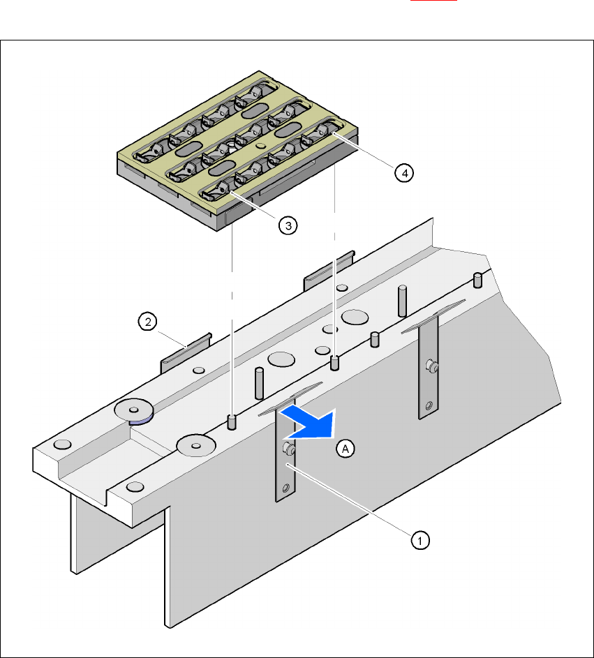
7.1.2.8 Changing the magazine
Æ To remove the magazine, push the spring hook (item 1 in Fig. 7.1 - 16) away from the mag-
azine. Lift the magazine out of the carrier.
7
Fig. 7.1 - 16 Changing the magazine
(1) Spring hook
(2) Retaining clamp
(3) Centering hole
(4) Slot
(A) Push the spring hook away from the magazine
User manual SIPLACE X-Series 7 Station extensions
Software Version SR.601.xx 11/2005 US Edition 7.1 Nozzle changer
391
PLEASE NOTE
Make sure that you insert the magazine so that the centering pins slide into the centering hole
(item 3 in Fig. 7.1 - 16) and slot (item 4 in Fig. 7.1 - 16). 7
Æ First place the side of the magazine with the numbered nozzles 1, 2, 3 and 4 on the base.
The retaining clamp (item 2 in Fig. 7.1 - 16
) must slide into the slot in the magazine.
Æ Push the spring hook away from the magazine.
Æ Press the magazine so that it lies flat on the base, then release the spring hook. The spring
hook must latch into place.
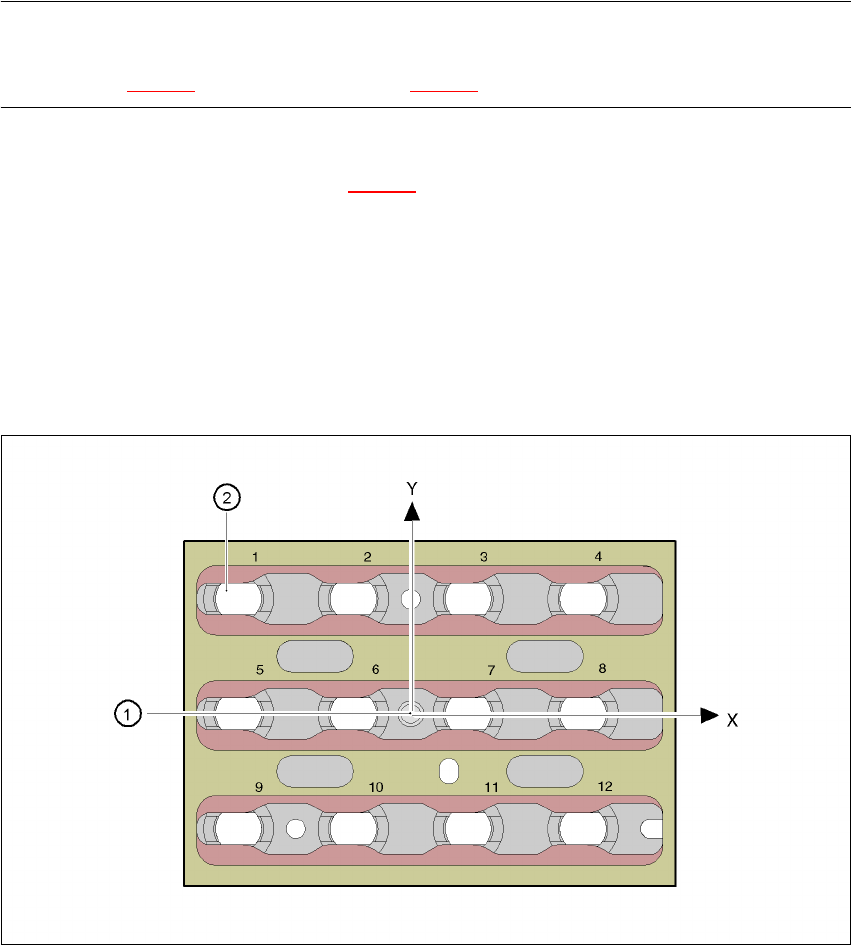
7.1.2.9 Position detection
Every magazine of the nozzle changer has a positioning fiducial for position detection.
7
Fig. 7.1 - 17 Nozzle changer - Position detection
(1) Positioning fiducial
(2) Position of the nozzles in the magazine relative to the positioning fiducial