X3_X4_Series machine - 第393页
User manual SIPLAC E X-Series 7 Station extensions Software Vers ion SR.601.xx 11/ 2005 US Ed ition 7.1 Nozzle changer 393 7.1.3 Nozzle changer for t he 6-se gment Colle ct&Place head Item no. 001 196 62-xx This no z…
7 Station extensions User manual SIPLACE X-Series
7.1 Nozzle changer Software Version SR.601.xx 11/2005 US Edition
392
7.1.2.10 "Row 2" nozzle changers for the 12-segment Collect&Place head
Item no. 00119663-xx
The "row 2" nozzle changer may be installed at the following locations:
X4 placement machine: Locations 1, 2, 3 and 4 (see Fig. 7.1 - 11
, page 383)
X3 placement machine: Locations 1, 3 and 4 (see Fig. 7.1 - 12
, page 384)
X2 placement machine: Locations 1 and 3 (see Fig. 7.1 - 13
, page 385)
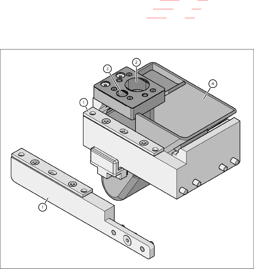
The retrofit package contains an assembly kit and a nozzle take-off device with reject bin, in ad-
dition to the nozzle changer.
7
Fig. 7.1 - 18 Assembly kit for the "row 2" nozzle changer
(1) Assembly kit for the "row 2" nozzle changer
(2) Nozzle take-off device for type 8xx nozzles
(3) Nozzle take-off device for type 9xx nozzles
(4) Nozzle reject bin
User manual SIPLACE X-Series 7 Station extensions
Software Version SR.601.xx 11/2005 US Edition 7.1 Nozzle changer
393
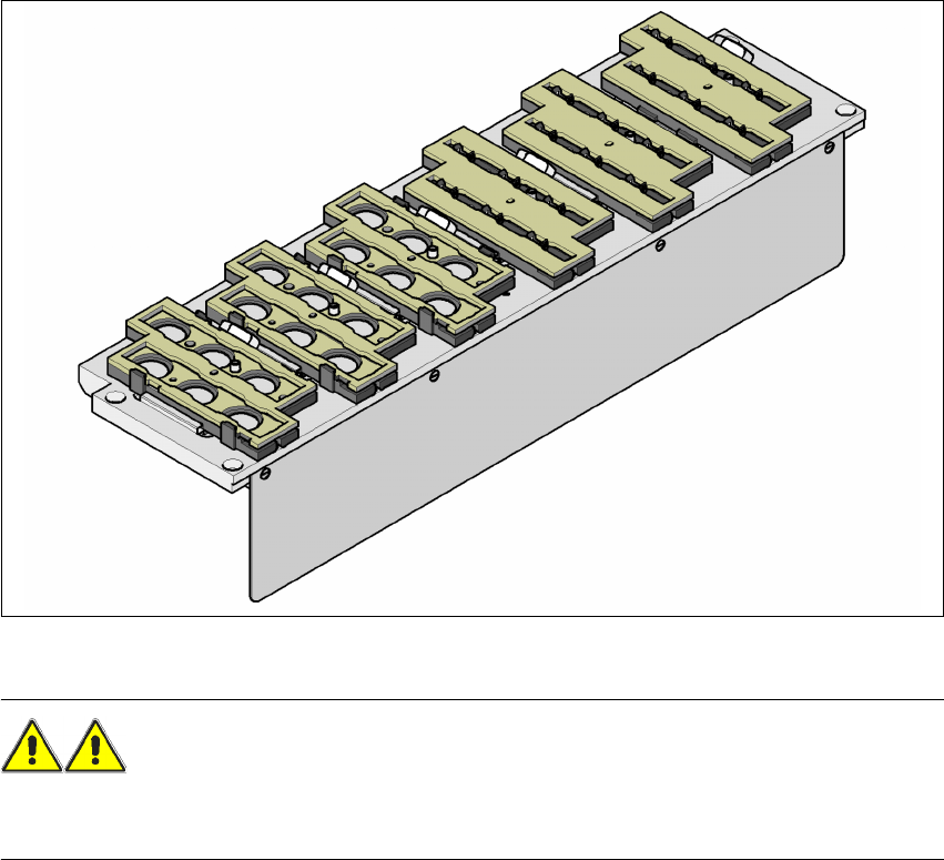
7.1.3 Nozzle changer for the 6-segment Collect&Place head
Item no. 00119662-xx
This nozzle changer can hold up to 6 magazines, each with 6 nozzle holders. There are two types
of magazine available: magazines for type 8xx nozzles and magazines for type 9xx nozzles. The
magazines are seated on a common support. They are centered using two parallel pins and fixed
in place with clips.
7
Fig. 7.1 - 19 Nozzle changer for the 6-segment Collect&Place head
WARNING 7
Only install the associated nozzle changer for each placement head. There is a risk of head
crashes with mixed configurations.
7 Station extensions User manual SIPLACE X-Series
7.1 Nozzle changer Software Version SR.601.xx 11/2005 US Edition
394
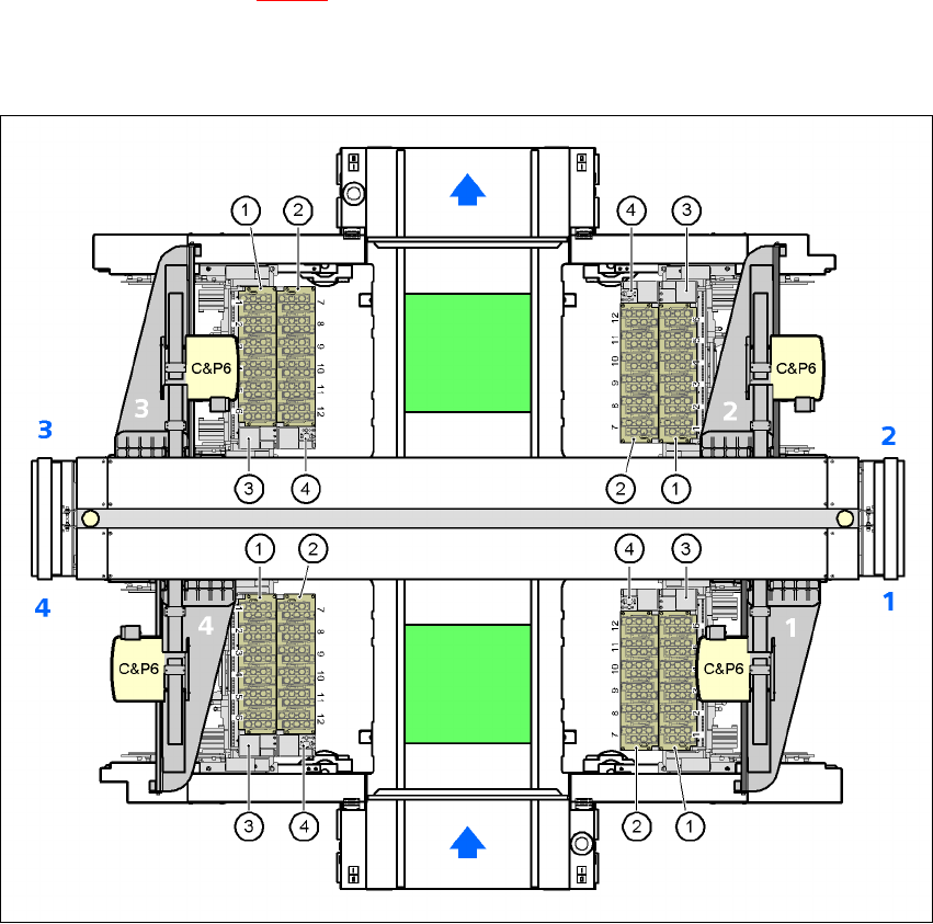
7.1.3.1 Position of the nozzle changers for the C&P6 head on the X4 machine
1 or 2 nozzle changers may be installed at locations 1, 2, 3, and 4 for the 6-segment Collect&Place
head (items 1 and 2 in Fig. 7.1 - 20
). One nozzle changer may be installed at location 2. This gives
a total capacity of 8 nozzle changers with 48 magazines and a total of 288 nozzle holders.
7
Fig. 7.1 - 20 Position of the nozzle changers for the C&P6 head on the X4 machine
(1) "Row 1" nozzle changer
(2) "Row 2" nozzle changer
(3) Reject bin for components
(4) Take-off device and reject bin for nozzles
(5) Nozzle magazine