X3_X4_Series machine - 第396页
7 Station extensions User manual SIPLACE X-S eries 7.1 Nozzle changer Software Version S R.601.xx 11/2005 US Edition 396 7.1.3.3 Pos ition of the nozzle changers f or the C&P6 head on the X2 mac hine 1 or 2 noz zle c…
User manual SIPLACE X-Series 7 Station extensions
Software Version SR.601.xx 11/2005 US Edition 7.1 Nozzle changer
395
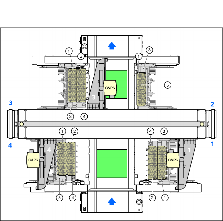
7.1.3.2 Position of the nozzle changers for the C&P6 head on the X3 machine
1 or 2 nozzle changers may be installed at locations 1, 3, and 4 for the 6-segment Collect&Place
head (items 1 and 2 in Fig. 7.1 - 21
). One nozzle changer may be installed at location 2. This gives
a total capacity of 7 nozzle changers with 42 magazines and a total of 252 nozzle holders.
7
Fig. 7.1 - 21 Position of the nozzle changers for the C&P6 head on the X3 machine
(1) "Row 1" nozzle changer
(2) "Row 2" nozzle changer
(3) Reject bin for components
(4) Take-off device and reject bin for nozzles
(5) Nozzle magazine
7 Station extensions User manual SIPLACE X-Series
7.1 Nozzle changer Software Version SR.601.xx 11/2005 US Edition
396
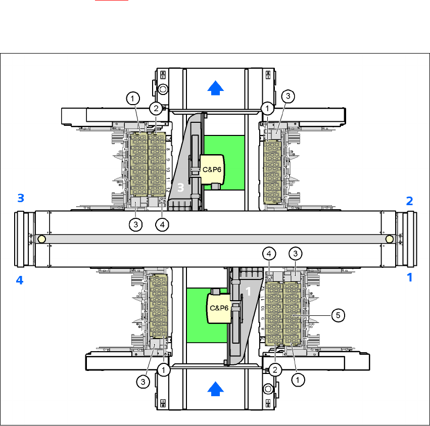
7.1.3.3 Position of the nozzle changers for the C&P6 head on the X2 machine
1 or 2 nozzle changers may be installed at locations 1 and 3 for the 6 segment Collect&Place head
(items 1 and 2 in Fig. 7.1 - 22
). A nozzle changer may be installed at locations 2 and 4. This gives
a total capacity of 6 nozzle changers with 36 magazines and a total of 216 nozzle holders.
7
Fig. 7.1 - 22 Position of the nozzle changers for the C&P6 head on the X2 machine
(1) "Row 1" nozzle changer
(2) "Row 2" nozzle changer
(3) Reject bin for components
(4) Take-off device and reject bin for nozzles
(5) Nozzle magazine
7
User manual SIPLACE X-Series 7 Station extensions
Software Version SR.601.xx 11/2005 US Edition 7.1 Nozzle changer
397
7.1.3.4 Technical data
7
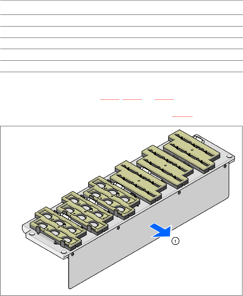
7.1.3.5 Assembly
The "Row 1" nozzle changer (see Figs. 7.1 - 22, 7.1 - 21 and 7.1 - 20) is fixed to the component
trolley docking unit. There is an additional assembly kit for the "row 2" nozzle changer. This kit
consists of the take-off device and the nozzle reject bin (see section 7.1.3.10
).
7
Fig. 7.1 - 23 Assembly position
(1) Cover plate pointing toward the PCB conveyor
7
Æ Align the nozzle changer so that the cover plate (item 1) points toward the PCB conveyor.
Nozzle changer for the 6-segment Collect&Place head
Dimensions (length x width x height) 448 x 122.5 x 97.7 mm³
Number of nozzle holders 6
Nozzle types 8 xx, 9 xx
Time required to open and close the locking plate < 200 ms
Compressed air connection 0.48 MPa (4.8 bar)