X3_X4_Series machine - 第413页
User manual SIPLAC E X-Series 7 Station extensions Software Version SR.601.xx 11/2005 US Edition 7.3 Component camera for the TwinHead, FC camera 413 7.3.1.2 Position of the component vision cameras for the T winHead on …
7 Station extensions User manual SIPLACE X-Series
7.3 Component camera for the TwinHead, FC camera Software Version SR.601.xx 11/2005 US Edition
412
7.3.1.1 Position of the component vision cameras for the TwinHead on the
X3 placement machine
7
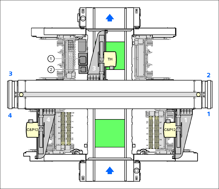
Fig. 7.3 - 2 Position of the component vision cameras for the TwinHead on the X3 placement machine
(1) Assembly position for the CO vision camera (stationary, P&P (type 33) 55 x 45), location 3
(2) Assembly position for the CO vision camera (stationary, P&P (type 25) 16 x 16), location 3
User manual SIPLACE X-Series 7 Station extensions
Software Version SR.601.xx 11/2005 US Edition 7.3 Component camera for the TwinHead, FC camera
413
7.3.1.2 Position of the component vision cameras for the TwinHead on the
X2 placement machine
7
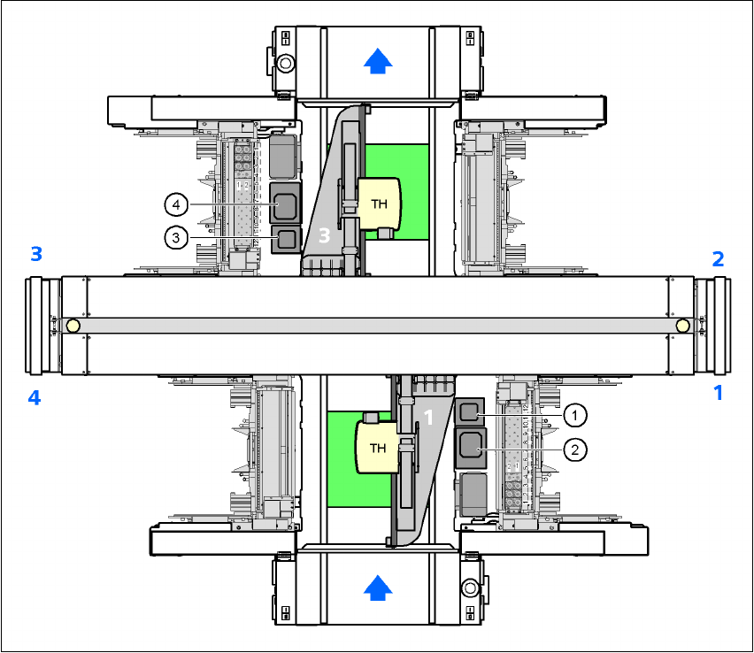
Fig. 7.3 - 3 Position of the component vision cameras for the TwinHead on the X2 placement machine
(1) Assembly position for the CO vision camera (stationary, P&P (type 25) 16 x 16), location 1
(2) Assembly position for the CO vision camera (stationary, P&P (type 33) 55 x 45), location 1
(3) Assembly position for the CO vision camera (stationary, P&P (type 25) 16 x 16), location 3
(4) Assembly position for the CO vision camera (stationary, P&P (type 33) 55 x 45), location 3
7 Station extensions User manual SIPLACE X-Series
7.3 Component camera for the TwinHead, FC camera Software Version SR.601.xx 11/2005 US Edition
414
7.3.1.3 Technical data
7
7
7
7
7.3.2 Safety instructions for the TwinHead component cameras during
a placement head change
WARNING 7
When the placement head is changed from the TwinHead to the Collect&Place head, the Twin-
Head's component cameras (stationary, P&P, type 33, 55 x 45, and type 25, 16 x 16) must be
removed, otherwise the Collect&Place head will collide with the camera housings.
Component dimensions 0.2 x 0.2 mm² up to 16 x 16 mm² for single component measurement
Range of components 0201 to SO, PLCC, QFP, sockets, plugs, BGA, special components,
bare dies, flip-chips, shields
Min. lead pitch 0.25 mm
Min. ball pitch 0.14 mm
Min. ball diameter 0.08 mm
Field of vision 19 x 19 mm²
Method of illumination Front-lighting (6 levels, programable as required)