X3_X4_Series machine - 第417页
User manual SIPLAC E X-Series 7 Station extensions Software Vers ion SR.601.xx 11/ 2005 US Ed ition 7.5 PCB barcode scanner 417 7.5 PCB barc ode scanner Item no. 001 196 82-xx 1D PCB bar code s canner Item no. 001 196 79…

7 Station extensions User manual SIPLACE X-Series
7.4 Multicolor PCB camera, type 24, digital Software Version SR.601.xx 11/2005 US Edition
416
7.4.3 Type of illumination
The following types of illumination can be selected on the multicolor PCB camera:
– White lighting
This type of illumination is used for standard PCBs with tinned fiducials.
– Blue oblique lighting
In most cases, this can be used to greatly improve the contrast with bright fiducials on a light
base material, such as ceramic or CEM. Fiducials covered with solder resist can also be de-
tected better on a light background.
– Infrared lighting
This type of illumination is particularly useful for fiducials that are covered with solder resist
or for fiducials on flex materials. It is also sometimes possible to improve detection of silver/
platinum fiducials on ceramic. This should be tested by carrying out a test centering or place-
ment run.
7.4.4 Fiducial and ink spot criteria
The fiducials and ink spot criteria are described in sections 3.11.5.3 and 3.11.5.4, page 162.
User manual SIPLACE X-Series 7 Station extensions
Software Version SR.601.xx 11/2005 US Edition 7.5 PCB barcode scanner
417
7.5 PCB barcode scanner
Item no. 00119682-xx 1D PCB barcode scanner
Item no. 00119679-xx 2D PCB barcode scanner
Item no. 00119684-xx PCB barcode scanner assembly kit
7.5.1 Overview
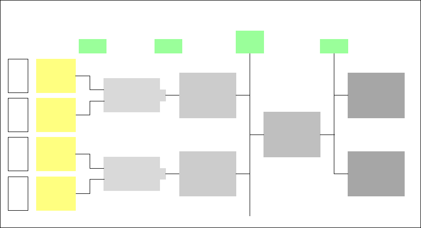
The PCB barcode scanner is used to automatically record and decode barcodes on PCBs. The
PCB barcode scanner sends the read data via its serial interface to the transport controller and
then for further processing to the machine controller via the CAN bus.
Fig. 7.5 - 1 PCB barcode block diagram
7
The PCB barcode scanners are installed on the input side of the placement machine on the PCB
conveyor. Up to four devices can be retrofitted to each machine. The barcode scanners are fitted
so that the barcode labels on the topside and underside of the PCBs can be scanned on both
tracks of the dual conveyor.
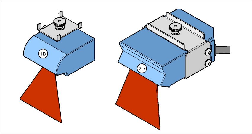
There are two variants of the barcode scanner:
– 1D barcode scanner
This barcode scanner processes barcodes. 7
– 2D barcode scanner
Device number
1
Barcode
scanner
topside
Distribution
board
Transport
controller,
right
Barcode
scanner
underside
2
3
Barcode
scanner
topside
Distribution
board
Transport
controller,
left
Barcode
scanner
underside
4
Machine
controller
Station
computer
SIPLACE Pro
computer
LAN
CAN
bus
V-24V-24
7 Station extensions User manual SIPLACE X-Series
7.5 PCB barcode scanner Software Version SR.601.xx 11/2005 US Edition
418
This barcode scanner processes matrix code. Matrix code is primarily used when there is
not enough space for barcode labels. The 2D barcode scanner also reads conventional bar-
codes. 7
7
Fig. 7.5 - 2 1D and 2D barcode scanners
The PCB barcode scanners are fixed to the top and bottom profiled rail using retainers. These can
be positioned as required on the profiled rails, and aligned with respect to the barcode labels. De-
pending on the position of the barcode strips, the barcode scanner can be attached in a few simple
steps so that the strips can be read parallel to or across the PCB transport direction.
7.5.2 Description of the functions
The SIPLACE PCB barcode scanner supports the flexible manufacture of SMD products, and in-
creases placement reliability. It recognizes all the code types conventionally used in industrial ap-
plications.
The laser scanner reads the barcode label on the topside or underside of each incoming PCB as
they are transported onto the input conveyor. The SIPLACE Pro computer uses the barcode in-
formation to automatically select the right placement program from the previously created barcode
assignment list (BA list), and sends it to the station. If a barcode filter is defined, only information
that is identified as relevant within the barcode is compared. This procedure is carried out time
neutrally during placement of the PCB already in the machine. If several PCBs with the same bar-
code enter in succession, the program is only transferred the first time. The following requirements
apply to all products to be produced using the PCB barcode:
– The component set-up must be identical on all the machines on the line
– All PCBs must be of the same width