X3_X4_Series machine - 第419页
User manual SIPLAC E X-Series 7 Station extensions Software Vers ion SR.601.xx 11/ 2005 US Ed ition 7.5 PCB barcode scanner 419 7.5. 3 T ec hnical da t a – 1D barcode scanner 7 7 7 7.5. 4 T ec hnical da t a – 2D barcode …
7 Station extensions User manual SIPLACE X-Series
7.5 PCB barcode scanner Software Version SR.601.xx 11/2005 US Edition
418
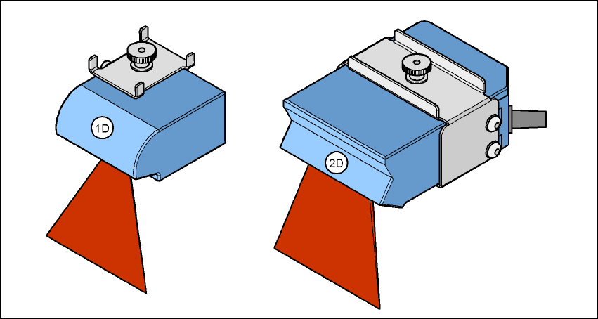
This barcode scanner processes matrix code. Matrix code is primarily used when there is
not enough space for barcode labels. The 2D barcode scanner also reads conventional bar-
codes. 7
7
Fig. 7.5 - 2 1D and 2D barcode scanners
The PCB barcode scanners are fixed to the top and bottom profiled rail using retainers. These can
be positioned as required on the profiled rails, and aligned with respect to the barcode labels. De-
pending on the position of the barcode strips, the barcode scanner can be attached in a few simple
steps so that the strips can be read parallel to or across the PCB transport direction.
7.5.2 Description of the functions
The SIPLACE PCB barcode scanner supports the flexible manufacture of SMD products, and in-
creases placement reliability. It recognizes all the code types conventionally used in industrial ap-
plications.
The laser scanner reads the barcode label on the topside or underside of each incoming PCB as
they are transported onto the input conveyor. The SIPLACE Pro computer uses the barcode in-
formation to automatically select the right placement program from the previously created barcode
assignment list (BA list), and sends it to the station. If a barcode filter is defined, only information
that is identified as relevant within the barcode is compared. This procedure is carried out time
neutrally during placement of the PCB already in the machine. If several PCBs with the same bar-
code enter in succession, the program is only transferred the first time. The following requirements
apply to all products to be produced using the PCB barcode:
– The component set-up must be identical on all the machines on the line
– All PCBs must be of the same width

User manual SIPLACE X-Series 7 Station extensions
Software Version SR.601.xx 11/2005 US Edition 7.5 PCB barcode scanner
419
7.5.3 Technical data – 1D barcode scanner
7
7
7
7.5.4 Technical data – 2D barcode scanner
7
Laser diode Red light
Wave length 670 nm
Laser class Class 2, as per DIN EN 60825-1:2001
Scanning frequency 400 ... 1200 Hz
Resolution 0.15 mm ... 0.5 mm
Code types Code 39, Code 128, Code 93,
Codabar, EAN, EAN 128, UPC,
2/5 Interleaved, Pharma Code
(others available on request)
Barcode length
Single conveyor
Dual conveyor, asynchronous
Dual conveyor, synchronous
Max. 40 characters
Max. 40 characters
Max. 2 x 12 characters
Optical display 4 x LED function display
Audible indicator Buzzer
Data interface RS232, RS 422/485
Electrical connection 15-pin D-Sub HD connector
Operating voltage 10 VDC ... 30 VDC
Degree of protection IP65
Laser diode Red light
Wave length 650 nm
Laser class Class 2, as per DIN EN 60825-1:2001
Scanning frequency 100 ... 15 kHz
Resolution 0.17 mm ... 0.5 mm
2D code types Data Matrix ECC 200
2D barcode length
Single conveyor
Dual conveyor, asynchronous
Dual conveyor, synchronous
Max. 40 characters
Max. 40 characters
Max. 2 x 12 characters
1D code types Code 39, Code 128,
Codabar, EAN, EAN 128, UPC,
2/5 Interleaved, Pharma Code
(others available upon request)
7 Station extensions User manual SIPLACE X-Series
7.5 PCB barcode scanner Software Version SR.601.xx 11/2005 US Edition
420
7
7
7
7
7
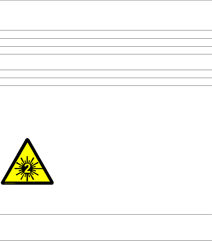
7.5.5 Warning label W216 on the cover of the PCB input side
7
Warning label W216 "Laser class 2" on the cover of the PCB input side,
item no. 03010316-01 (number per placement machine: 1)
PLEASE NOTE 7
When you install a PCB barcode scanner on the placement machine, you must attach laser
warning label W206 contained in the retrofit kit to the cover on the PCB input side.
7
1D barcode length
Single conveyor
Dual conveyor, asynchronous
Dual conveyor, synchronous
Max. 40 characters
Max. 40 characters
Max. 2 x 12 characters
Optical display 4 x LED function display
Audible indicator Buzzer
Data interface RS232, RS 422/485, Ethernet
Electrical connection 15-pin D-Sub HD connector
RJ45 connector 10baseT
Operating voltage 10 VDC ... 30 VDC
Degree of protection Class 3
7
7
7
7
7
7
LASER RADIATION!
Do not look into beam
Laser class 2