X3_X4_Series machine - 第433页
User manual SIPLAC E X-Series 7 Station extensions Software Version SR.601.xx 11/2005 US Edition 7.12 Coplanarity laser module 433 7.12 C opla narit y laser module Item no. 001 197 19-xx 7.12.1 Description of the functio…

7 Station extensions User manual SIPLACE X-Series
7.11 Component sensor for the C&P12 head Software Version SR.601.xx 11/2005 US Edition
432
PLEASE NOTE 7
If you are placing 0201 components with the 906 nozzle, it is essential to use the component sen-
sor since no vacuum measurements are possible. 7
Using the component sensor can improve the dpm rate even when placing other small compo-
nents, such as 0402 or 0603 components. When you select a component sensor from the pack-
age form list, remember that the component can only be placed on machines that are equipped
with that component sensor.
If you wish to test components with the component sensor, then it must be configured on the line.
The following alternatives are then available:
New set-up The set-up optimization automatically assigns the components to the
component sensor, if the sensor is installed.
Old set-up A new GF number is assigned to components to be checked with the
component sensor.
Central data management If not every machine on the line is equipped with the component sen-
sor, then a new package form number is assigned for every compo-
nent to be checked with the component sensor.
PLEASE NOTE 7
– The component sensor may only be retrofitted by SIEMENS AG service engineers.
– Recalibrate the 12-segment C&P head with the SITEST program after installing the compo-
nent sensor.
User manual SIPLACE X-Series 7 Station extensions
Software Version SR.601.xx 11/2005 US Edition 7.12 Coplanarity laser module
433
7.12 Coplanarity laser module
Item no. 00119719-xx
7.12.1 Description of the functions
The coplanarity laser module is used to measure vertical bending of the leads. The lead length is
measured without contact using the laser triangulation principle.
7
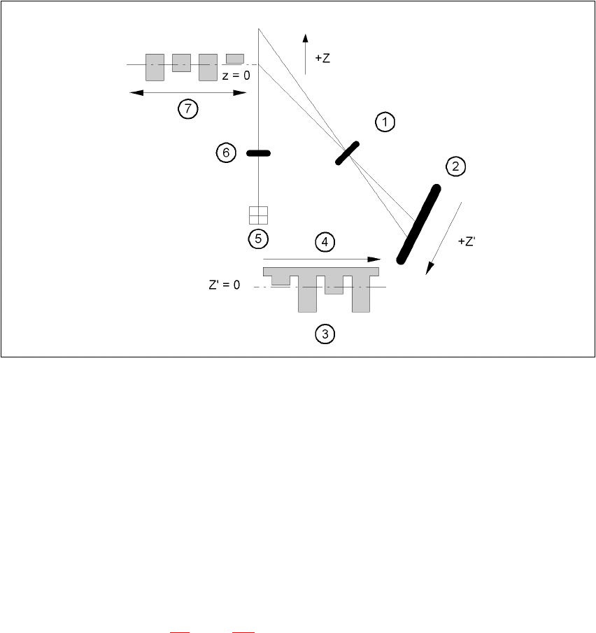
Fig. 7.12 - 1 Laser triangulation measurement principle
(1) Receiver lens
(2) Detector
(3) Measuring signal
(4) Time t
(5) Laser
(6) Transmitter lens
(7) Travel direction
The TwinHead picks up the component to be checked, centers it optically using the component
vision camera (see section 7.3
, page 411) and moves all four sides one after another over the
fixed laser beam of the coplanarity laser module. In this way, every lead is scanned from below
by the laser beam. The laser light scattered by the underside of the lead is recorded by a sensor,
7 Station extensions User manual SIPLACE X-Series
7.12 Coplanarity laser module Software Version SR.601.xx 11/2005 US Edition
434
and is then used to calculate the exact position of the lead with respect to the PCB. The position
values thus calculated are compared against the limit value specified by the user. If they exceed
this value, the component is disposed of or returned.
The coplanarity laser module is used in combination with the optical component centering mode.
Components with bent or missing leads are detected and disposed of, if necessary.
7.12.2 Technical data
Component range: Can be used for ’gull wing’ package forms, spacing > 0.3 mm
and maximum component size 55 x 55 mm². Other restric-
tions are associated with the machine configuration.
Measuring principle: Contact-free measurement by laser triangulation
Algorithm functions: JEDEC standard - calculation of the placement plane; all
deviations are determined in relation to this plane. If the com-
ponent is angled with respect to the vacuum nozzle, as can
happen if an adapter is used, then it will have no influence
over the choice between ‘good’ and ‘bad’.
Measuring range: 3 mm
Start of measuring range (SMR) 24 mm
Reference distance
(Middle of measuring range MMR) 25.5 mm
End of measuring range (EMR) 27 mm
Linearity ± 1.5 µm
Resolution: 0.15 µm
Measuring rate 10 kHz
Wave length 670 nm, red
Max. output 1 mW
Laser class 2
Permissible ambient light: 30,000 lx
Light spot diameter SMR 80 µm
MMR 35 µm
EMR 80 µm
Operating temperature: 0°C ... + 50°C
Storage temperature - 20°C ... + 70°C
Sensor protection class IP 65
Controller protection class IP 50
Supply voltage 24 VDC (± 15%, max. 500 mA)
Output, digital RS 422, 687.5 kBaud