X3_X4_Series machine - 第443页
User manual SIPLAC E X-Series Index 11/2005 US Edition 443 Index 12 mm X tape fee der modu le 294 12/16 mm S tape feeder mo dule 333 12-s egment C ollect& Place he ad angular ac curacy 132 C&P com ponent came ra,…
7 Station extensions User manual SIPLACE X-Series
7.14 SIPLACE productivity lift Software Version SR.601.xx 11/2005 US Edition
442
7.14.3 Advantages of the productivity lift
The productivity lift can raise the productivity of a line overall because it increases the placement
rates of the machines on the line.
7
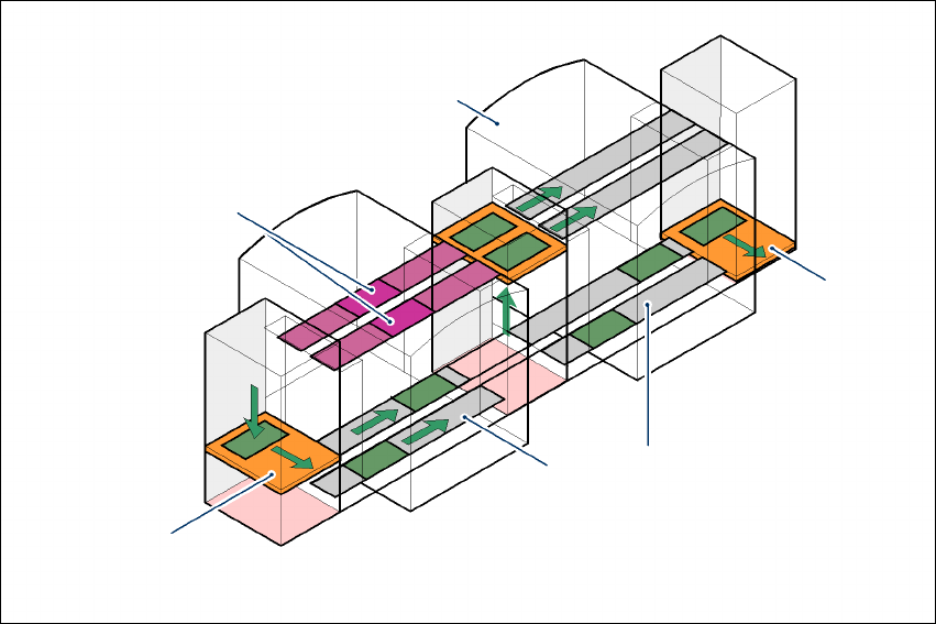
Fig. 7.14 - 3 Productivity lift – Avoiding stoppages
If lines are connected in parallel, individual machines may fail without bringing the entire line to a
standstill. It is also possible access individual machines while the rest of the line continues plac-
ing without interruption. This chaining increases the components to be placed per station and
minimizes conveyor idle times. This leads to an overall higher placement rate on the line.
This could be for
– process-related investigations or test operation
– programming PCB fiducials, package forms or test placements
– maintenance or repairs
– operating errors, such as not splicing tapes on in good time or missing components.
Another advantage is that the line can be reconfigured as required using the software, without
having to reset the machines.
Conveyor section, processing
Placement machine
Horizontal
and vertical lift
Underfloor
conveyor
Track change

User manual SIPLACE X-Series Index
11/2005 US Edition
443
Index
12 mm X tape feeder module 294
12/16 mm S tape feeder module
333
12-segment Collect&Place head
angular accuracy
132
C&P component camera, type 28 (18 x 18) digi-
tal or type 29 (27 x 27) digital, high resolution
129
checking and self-learning functions
130
component range
132
component sensor
430
component specification
132
description
129
description of the functions
130
DP axis
131
forced air valve
128
intermediate distributor board
129
nozzle types
132
set-down force
132
silencer
128
star axis
131
star drive - DR motor
129
star with 12 sleeves, star axis
128
technical data
132
turning station, DP axis
128
vacuum generator
128
valve adjustment drive
129
X/Y accuracy
132
Z axis
131
Z axis motor
129
16 mm X tape feeder module
295
1D PCB barcode scanner
417
20-nozzle Collect&Place head
"vacuum sensor holding circuit" board
120
angular accuracy
127
C&P component camera, type 23, 6 x 6, digital
121
component range
127
component sensor
121
component specification
127
compressed air connection for 20 Venturi
nozzles in the pick-up/placement and holding
circuit
120
DP drive
120
handle
121
intermediate distributor board
121
line for the exhaust air from the pressure control
valve
120
nozzle types
127
pressure control valve
120
return cylinder
120
set-down force
127
star motor
121
star with 20 nozzles
121
X/Y accuracy
127
Z motor
120
24 mm X tape feeder module
296
24/32 mm S DP tape feeder module for deep po-
ckets
335
24/32 mm S tape feeder module
334
2D PCB barcode scanner
417
3 x 8 mm S tape feeder module
331
3 x 8 mm S tape feeder module for 0201/0402 com-
ponents
332
32 mm X tape feeder module
297
44 mm S DP tape feeder module for deep pockets
337
44 mm S tape feeder module
336
44 mm X tape feeder module
298
56 mm S DP tape feeder module for deep pockets
339
56 mm S tape feeder module
338
56 mm X tape feeder module
299
6-segment Collect&Place head
angular accuracy
137
C&P component camera , type 29, 27 x 27
134
checking and self-learning functions
135
component range
137
component specification
137
description
135
description of the functions
135
DP axis
136
forced air valve
133
intermediate distributor board
134
nozzle types
137
set-down force
137
silencer
133
star axis
136
star drive - DR motor
134

Index User manual SIPLACE X-Series
11/2005 US Edition
444
star with 6 sleeves - star axis
133
technical data
137
turning station, DP axis
133
vacuum generator
133
valve adjustment drive
134
X/Y accuracy
137
Z axis
136
Z axis motor
134
72 mm S tape feeder module
340
72 mm X tape feeder module
300
8 mm S II tape feeder module
330
8 mm X tape feeder module
293
88 mm S tape feeder module
341
88 mm X tape feeder module
301
A
abbreviations 26
adapting the length of the SIPLACE X used tape
chute to the PCB conveyor height
241
adapting the SIPLACE HF component trolley to the
PCB transport height
243
changing the component trolley height
244
eye-bolt
244
eye-bolt, DIN 580 M12-St
245
holes in the guide columns for the transport
heights of 830 to 950 mm
243
lifting device
244
M12 hole for eye-bolt
245
punch, 8 mm
244
split pin
245
supporting block
245
table
243
tools and equipment
244
warning instructions
244
adapting the SIPLACE X-series component trolley
to the PCB transport height
237
assembly guide
239, 240
block
238
changing the component trolley height
239
component feeder table
238
eye
240
hexagon socket head screw
240
holes in the guide columns for the transport
heights of 900, 930 and 950 mm.
238
lifting device
239
M8 holes for fixing the assembly guide
238
M8 threaded hole in the component table
240
punch, 8 mm
239
split pin
240
supporting block
240
tools and equipment
239
warning instructions
238
adjusting screw M24x2x120 for adjusting the height
236
air cushion transport system
191, 234
allen key, size 10
191
allen key, size 19
191
ambient factors, permitted
100
angle for the cable gland
142, 186
angular accuracy
97
approach guard for the X component trolley on the
SIPLACE HF component trolley docking unit
280
assembly kit, PCB barcode scanner
417
assembly positions for the stationary P&P compo-
nent camera (type 33) 55 x 45
155
assembly trough
163
asynchronous transport mode
description
169
function
169
atmospheric humidity
100
authorized accessories
30
authorized employees.
90
automatic circuit breaker F1
82, 85
automatic width adjustment on the dual conveyor
171
avoiding track errors
272
axis unit
75
in the extension kit on the PCB output side
175
axis unit (X2)
202
axis unit (X3, X4)
217
axis unit X3, X4 (gantries 1 and 4)
back panel
228
connecting the plugs
229
electrical connection points
228
fitting
230
switch settings
229
axis unit, gantries 2 and 3 (X4)
202
axis unit, gantry 3 (X3)
202
B
board, inrush current limiter - servo unit 47