X3_X4_Series machine - 第72页
2 Operational safety User manual SIPLACE X-Series 2.6 Safety equipment Software V ersion SR.601.xx 11/2005 US Edition 72 2 Fig. 2.6 - 8 Emergenc y stop loops S tart button pressed No No Ye s No No Ye s Ye s No 2 Active P…
User manual SIPLACE X-Series 2 Operational safety
Software Version SR.601.xx 11/2005 US Edition 2.6 Safety equipment
71
2.6.4.2 Structure of the signaling circuit
The signaling contacts in the protective switches of protective covers, of cover flaps over the PCB
conveyor, of component trolleys and of emergency stop buttons are polled individually. All the sig-
naling contacts are closed when the machine is on standby. If a protective cover, for example, is
raised, the associated signaling contact opens. This change of state is signaled to the station com-
puter via the CAN bus. An error message to this effect appears on the user interface.
2.6.4.3 Description of the functions of the emergency stop loops
The following conditions must be fulfilled in order to start and operate the placement machine:
– all four component trolleys must be docked in and connected.
– all protective covers must be closed.
– both cover flaps over the PCB conveyor must be closed.
– both emergency stop buttons must be released.
– the cover flaps (option) over the feeder modules must be closed.
– the minimum operating pressure must have been reached.
– the "software enable" signal must be active. This ensures that the safety circuit is closed.
– the power supply must be sending 24 V to the Start buttons and the protective contactor com-
bination.
– If one of the Start buttons is now pressed, the protective contactor combination PCC K6 will
switch and activate the following components:
– 250 VDC link voltage for the servo amplifiers for the gantry axes
– 145 VDC link voltage for the star axes
– the axis unit receives a "Servo enable" signal for the servo amplifiers
– 34 VDC operating voltage is switched to the component trolleys.
– 24 VDC operating voltage is switched to the used tape cutters.
– the PCB conveyor control receives the enable signal for the PCB clamping, the PCB
stopper and the lifting table control.
The machine is then ready for use.
2 Operational safety User manual SIPLACE X-Series
2.6 Safety equipment Software Version SR.601.xx 11/2005 US Edition
72
2
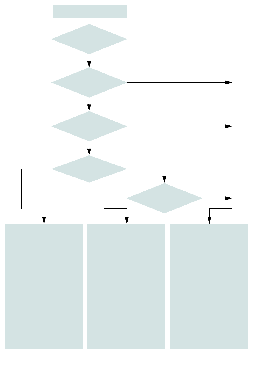
Fig. 2.6 - 8 Emergency stop loops
Start button pressed
No
No
Yes
No
No
Yes
Yes
No
2
Active
PCC*) Yes
Voltage
Y axis 250 VDC
X axis 250 VDC
Star axis 145 VDC
DP axis 40 VDC
Z axis 40 VDC
Active
PCB conveyor Yes
Lifting table Yes
PCB clamping Yes
Width adjustment Yes
Laser light barrier Yes
Used tape cutter Yes
Component trolley
dock. unit Yes
Yes
2
Active
PCC*) No
Voltage
Y axis 0 V
X axis 0 V
Star axis 0 V
DP axis 40 VDC
Z axis 40 VDC
Active
PCB conveyor Yes
Lifting table No
PCB clamping No
Width adjustment Yes
Laser light barrier No
Used tape cutter No
Component trolley
dock. unit Yes
2
Active
PCC*) No
Voltage
Y axis 0 V
X axis 0 V
Star axis 0 V
DP axis 40 VDC
Z axis 40 VDC
Active
PCB conveyor No
Lifting table No
PCB clamping No
Width adjustment No
Laser light barrier No
Used tape cutter No
Component trolley
dock. unit No
*) PCC protective contactor combination K6
Yes
Compressed
air min. 0.5 MPa
(5.0 bar)?
Emergency stop button
pressed?
Protective cover open ?
Component
trolley emergency stop cir-
cuit interrupted?
Barrier
activated on the user
interface?
User manual SIPLACE X-Series 2 Operational safety
Software Version SR.601.xx 11/2005 US Edition 2.6 Safety equipment
73
2.6.5 Hand guard at the component trolley locations, SIPLACE X-series
WARNING 2
All locations must be equipped with feeder modules in order to guarantee operational reliability. If
there are not enough feeder modules available, unassigned locations should be fitted with a
hand guard (dummy feeder module). When a waffle-pack tray holder is set up, the remaining
locations should be protected again with a hand guard.
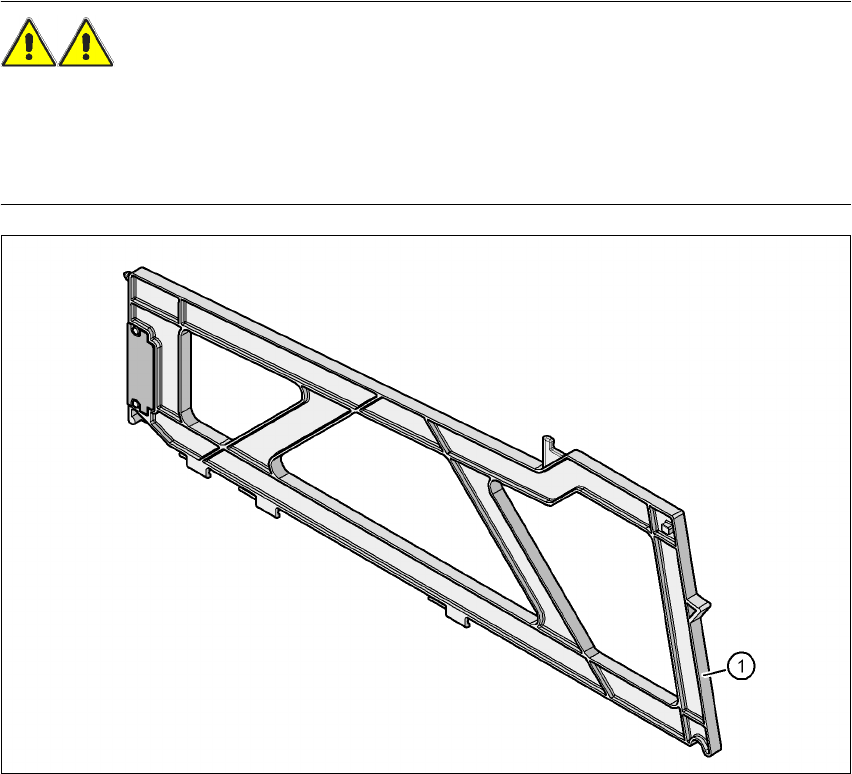
Fig. 2.6 - 9 Hand guard at the component trolley locations, SIPLACE X-series
2
(1) Hand guard for 1 location item no. 03028842-01
The hand guard fills one 8 mm location and can be replaced during placement.