X3_X4_Series machine - 第75页
User manual SIPLAC E X-Series 2 Operational safety Software Vers ion SR.601.xx 11/ 2005 US Ed ition 2.7 Residual voltages and discharge t imes in the ma chine 75 2.7 Residual v olt ages and discharge times in the machine…
2 Operational safety User manual SIPLACE X-Series
2.6 Safety equipment Software Version SR.601.xx 11/2005 US Edition
74
2.6.6 Hand guard at the component trolley locations, SIPLACE HF
WARNING 2
All locations must be equipped with feeder modules in order to guarantee operational reliability. If
there are not enough feeder modules available, unassigned locations should be fitted with a
hand guard (dummy feeder module). When a waffle-pack tray holder is set up, the remaining
locations have to be protected again with a hand guard.
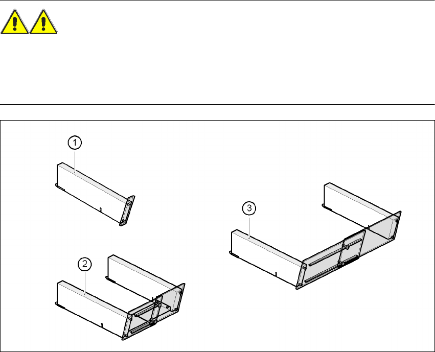
Fig. 2.6 - 10 Hand guard for component trolleys
2
(1) Hand guard for 1 location item no. 00116961-01
(2) Hand guard for 6 to 10 locations item no. 00116962-01
(3) Hand guard for 11 to 20 locations item no. 00116963-01
User manual SIPLACE X-Series 2 Operational safety
Software Version SR.601.xx 11/2005 US Edition 2.7 Residual voltages and discharge times in the machine
75
2.7 Residual voltages and discharge times in the
machine
If the emergency stop button is pressed or the placement system is switched off, the 250 VDC link
voltage for the gantry axes and the 145 VDC link voltage for the star axes are reduced to harmless
residual voltages in a very short time.
WARNING 2
The placement system is supplied with 3 x 208 VAC, 3 x 230 VAC, 3 x 380 VAC, 3 x 400 VAC or
3 x 415 VAC ± 5 %, 50/60 Hz mains voltage. This means that some parts of the system carry
potentially lethal voltages - even when switched off at the main power switch. Incorrect handling
of the placement system can therefore result in death or severe injury or considerable damage to
equipment.
Æ Always follow the applicable accident prevention and DIN regulations (particularly DIN EN 60
204, part 1).
Æ The guards over the power supply unit and the axis unit must ONLY be opened by appropri-
ately qualified and trained personnel.
2
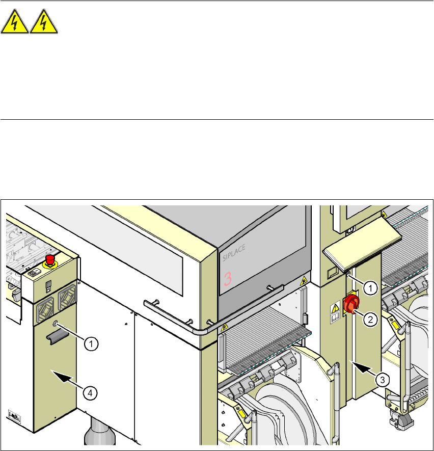
Fig. 2.7 - 1 Power supply unit
(1) Padlock with bolt in the cover
(2) Main power switch
(3) Power supply unit behind the cover
(4) Axis unit
2 Operational safety User manual SIPLACE X-Series
2.7 Residual voltages and discharge times in the machine Software Version SR.601.xx 11/2005 US Edition
76
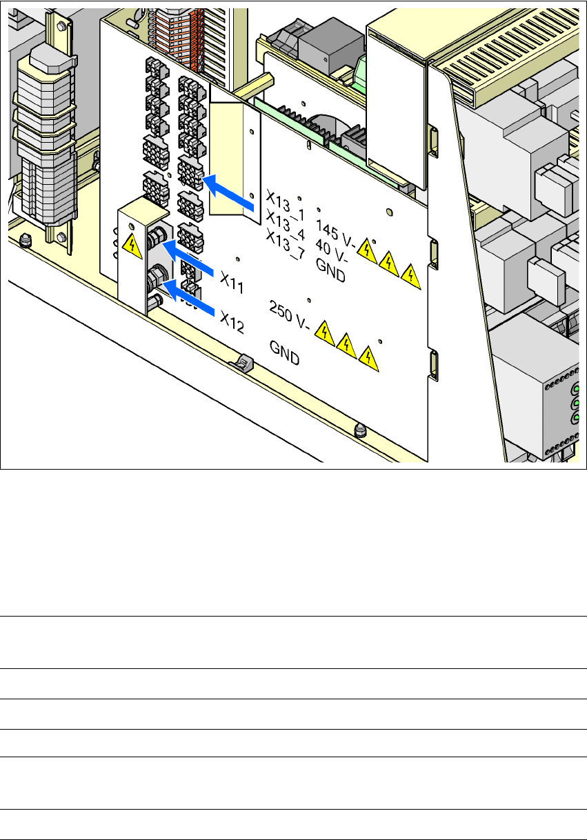
Fig. 2.7 - 2 Measuring points on the power supply unit
2
2.7.1 Operating voltages, residual voltages and discharge times after pressing
the emergency stop button
2
2
Pins X11 and X13_1
measured to X12 (GND)
Voltage in
normal mode
Residual voltage after
emergency stop
Discharge
times
X11 + 250 VDC < 10 VDC 7 sec
X13_1 + 145 VDC < 10 VDC 50 sec
Pin X13_4
measured to pin X3_7 (-)
Voltage in
normal mode
Residual voltage after
emergency stop
Discharge
times
X13_4 + 40 VDC + 40 VDC -