X3_X4_Series machine - 第93页
User manual SIPLAC E X-Series 3 Technical data Software Vers ion SR.601.xx 11/ 2005 US Ed ition 3.1 Descript ion of the machine 93 3 T echnical dat a 3.1 Description of the machine The SMD placemen t system s from t he S…
2 Operational safety User manual SIPLACE X-Series
2.11 ESD guidelines Software Version SR.601.xx 11/2005 US Edition
92
Always place the modules on a conductive surface (table with an ESD coating, conductive ESD
foam, ESD bag or container).
Do not bring modules near visual display units, monitors or televisions. Keep them at least 10 cm
away from the screen.
2.11.4 Measurements and modifications to ESD modules
Do not take measurements on the modules unless the following conditions are fulfilled:
– the measuring device is earthed (e.g. via PE conductors) or
– you discharge the measuring head just before taking measurements with a potential-free
measuring device (e.g. by touching an unpainted metal part of the controller casing).
Æ Always use an earthed soldering iron if you carry out any soldering work.
2.11.5 Dispatching ESD modules
Æ Always store modules and components in conductive packaging (e.g. metallized plastic bags
or metal sleeves) and dispatch them in conductive packaging.
If the packaging is not conductive, place the modules in a conductive envelope before packag-
ing. Use conductive expanded rubber, ESD bags, domestic aluminum foil or paper, for exam-
ple. NEVER use plastic bags or film. 2
Æ If the module has integral batteries, ensure that the conductive packaging does not touch or
short-circuit the battery terminals and, if necessary, first cover the terminals with insulating
tape or material.
User manual SIPLACE X-Series 3 Technical data
Software Version SR.601.xx 11/2005 US Edition 3.1 Description of the machine
93
3 Technical data
3.1 Description of the machine
The SMD placement systems from the
SIPLACE X-series
are characterized by their high config-
uration flexibility, excellent placement rate and maximum precision. The machines cover the SMD
spectrum of components from 0201 to 125 x 100 mm² with a high placement rate.
Two placement methods are used:
–the
Collect&Place
method with Collect & Place heads for components from size 0201 to fine-
pitch
–the
Pick&Place
method with the SIPLACE TwinHead for fine-pitch and OSC components
3
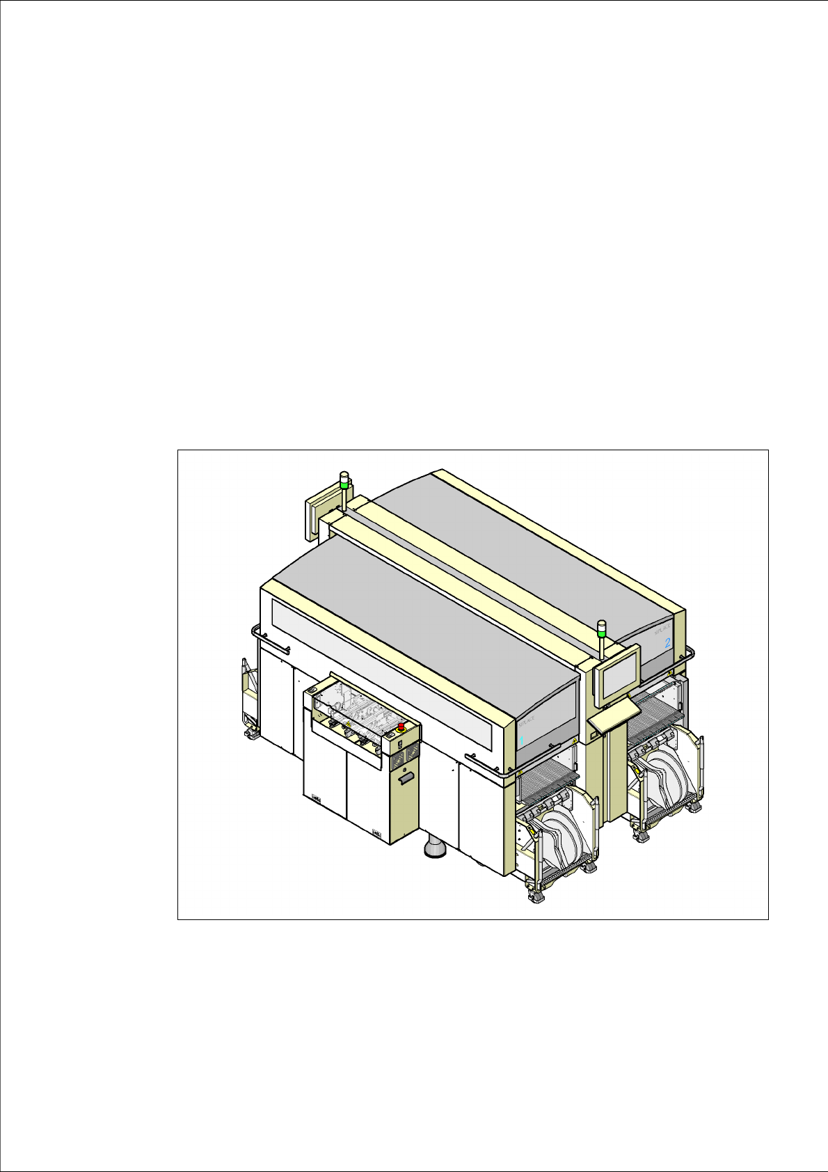
Fig. 3.1 - 1 X4 placement machine, overview

3 Technical data User manual SIPLACE X-Series
3.1 Description of the machine Software Version SR.601.xx 11/2005 US Edition
94
The placement machines are based on a torsionally-rigid and vibration-damped cast steel ma-
chine frame. This guarantees an excellent production quality and less environmental pollution for
employees since the noise of shaking and vibration are reduced to a minimum.
The X2 placement machine has two gantries. The X3 placement machine has three gantries,
while the X4 machine has four gantries. There is a placement head on each gantry. These can be
quickly and accurately positioned by linear motors, moving independently of one another in the X
and Y directions.
According to the head modularity principle developed by Siemens, the placement heads can be
quickly and easily changed. An overview of the placement head configuration can be found in sec-
tion 3.7
, page 117.
There are four locations for feeding components. Up to four component trolleys or alternatively
one or two matrix tray changers can be docked into X2 machines in place of the component trolley.
On X3 machines, a matrix tray changer may be used in place of a component trolley.
The placement heads fetch the components from the fixed feeder modules on the component trol-
ley or from the trays in the matrix tray changer, and place the PCBs, which are also stationary.
The placement machines from the X-series have two placement areas:
– on the single conveyor, one or two PCBs can be placed concurrently.
– on the dual conveyor, up to four PCBs can be placed concurrently.
The principle of the "stationary component supply" and "stationary PCB", which has proved most
suitable for all SIPLACE placement machines, has a number of significant advantages:
– There are no downtimes for topping up components or splicing tapes.
– The vibration-free component feeder means that even the smallest components (e.g. 0201)
are picked up reliably.
– The PCB, which does not move during the placement process, prevents the components slip-
ping.
– The combination of placement heads with nozzle changers always guarantees an optimum
nozzle configuration for every placement process, thus minimizing traversing paths and opti-
mizing the placement sequence.
High flexibility, cost-effectiveness and set-up reliability combine to ensure that the SIPLACE X-
series provides high productivity. Minimum down times increase utilization and thus help to in-
crease productivity.