X3_X4_Series machine - 第96页
3 Technical data User manual SIPLACE X-Series 3.2 Performance dat a for the mac hines Software Version S R.601.xx 11/2005 US Edition 96 3.2 Performanc e dat a for the machine s 3 T ypes of placemen t head 20-s egment Col…
User manual SIPLACE X-Series 3 Technical data
Software Version SR.601.xx 11/2005 US Edition 3.1 Description of the machine
95
3
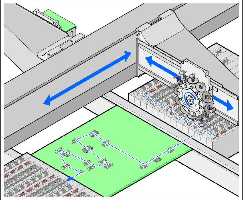
Fig. 3.1 - 2 Placement principle using the Collect&Place method
The following options are available to extend the machine's functionality:
– Additional component trolleys increase machine utilization since set-up times can be reduced
by carrying out preliminary set-up off the machine.
– The dual conveyor also increases machine utilization by eliminating non-productive PCB
transport times.
– Automatic nozzle changers speed up and optimize the nozzle configuration process.
– PCB barcode scanners allow the production set-up to be changed over when triggered by a
new product.
– Component barcode scanners optimize the set-up and refill checks.
– Large and sensitive components can be supplied in trays in add-on matrix tray changers.
– The productivity lift implements the concept of parallel placement, and thus improves the ratio
between productive and non-productive times.

3 Technical data User manual SIPLACE X-Series
3.2 Performance data for the machines Software Version SR.601.xx 11/2005 US Edition
96
3.2 Performance data for the machines
3
Types of placement head 20-segment Collect&Place head (C&P20)
12-segment Collect&Place head (C&P12)
6-segment Collect&Place head (C&P6)
SIPLACE TwinHead (TH)
SIPLACE X4 placement system
Number of gantries 4 (see Fig. 3.7 - 1
, page 117)
Placement head configu-
ration and placement rate
(Benchmark test)
Placement area 1 Placement area 2 Placement rate
C&P20 / C&P20 C&P20 / C&P20 80,000 comp./h
C&P20 / C&P20 C&P12 / C&P12 66,400 comp./h
C&P20 / C&P20 C&P12 / C&P6 60,300 comp./h
C&P20 / C&P20 C&P6 / C&P6 58,300 comp./h
C&P12 / C&P12 C&P12 / C&P12 52,800 comp./h
C&P12 / C&P12 C&P12 / C&P6 46,700 comp./h
C&P12 / C&P12 C&P6 / C&P6 44,700 comp./h
C&P12 / C&P6 C&P12 / C&P6 40,600 comp./h
C&P12 / C&P6 C&P6 / C&P6 38,600 comp./h
C&P6 / C&P6 C&P6 / C&P6 36,600 comp./h
SIPLACE X3 placement system
Number of gantries 3 (see Fig. 3.7 - 2
, page 118)
Placement head configu-
ration and placement rate
(Benchmark test)
Placement area 1 Placement area 2 Placement rate
C&P20 / C&P20 C&P20 60,000 comp./h
C&P20 / C&P20 C&P12 54,000 comp./h
C&P20 / C&P20 C&P6 49,300 comp./h
C&P20 / C&P20 TH 43,700 comp./h
C&P12 / C&P12 C&P12 40,400 comp./h
C&P12 / C&P12 C&P6 35,700 comp./h
C&P12 / C&P12 TH 30,100 comp./h
C&P12 / C&P6 C&P6 29,600 comp./h
C&P12 / C&P6 TH 24,000 comp./h
C&P6 / C&P6 C&P6 27,600 comp./h
C&P6 / C&P6 TH 22,000 comp./h
SIPLACE X2 placement system
Number of gantries 2 (see Fig. 3.7 - 3
, page 119)
Placement head configu-
ration and placement rate
(Benchmark test)
Placement area 1 Placement area 2 Placement rate
C&P20 C&P20 40,000 comp./h
C&P20 C&P12 34,000 comp./h
C&P20 C&P6 29,300 comp./h
C&P20 TH 23,700 comp./h

User manual SIPLACE X-Series 3 Technical data
Software Version SR.601.xx 11/2005 US Edition 3.2 Performance data for the machines
97
3
3
C&P12 C&P12 28,000 comp./h
C&P12 C&P6 23,300 comp./h
C&P12 TH 17,700 comp./h
C&P6 C&P6 18,600 comp./h
C&P6 TH 13,000 comp./h
TH TH 7,400 comp./h
Placement
positions
3,500 / gantry
Component
range
0.6 x 0.3 mm² (0201*) to 85 x 85 mm² / 125 x 10 mm²,
up to 200 x 125 mm² (with restrictions)
*) Smaller components, e.g. 01005, available on request
Component
height
C&P20: 4 mm
C&P12: 6 mm
C&P6: 8.5 mm
TH: 25 mm (larger heights available on request)
Placement
accuracy
C&P20
C&P12
C&P12
C&P6
TH
TH
± 41 µm (3 σ), ± 55 µm (4 σ)
± 45 µm (3 σ), ± 60 µm (4 σ)
± 41 µm (3 σ), ± 55 µm (4 σ)
± 45 µm (3 σ), ± 60 µm (4 σ)
± 26 µm (3 σ), ± 35 µm (4 σ)
± 22 µm (3 σ), ± 30 µm (4 σ)
CO camera, type 23 (6 x 6)
CO camera, type 28 (18 x 18)
CO camera, type 29 (27 x 27)
CO camera, type 29 (27 x 27)
CO camera, type 33 (55 x 45)
CO camera, type 25 (16 x 16)
Angular
accuracy
C&P20
C&P12
C&P12
C&P6
TH
TH
± 0.5° (3 σ), ± 0.7° (4 σ)
± 0.5° (3 σ), ± 0.7° (4 σ)
± 0.5° (3 σ), ± 0.7° (4 σ)
± 0.2° (3 σ), ± 0.3° (4 σ)
± 0.05° (3 σ), ± 0.07° (4 σ)
± 0.05° (3 σ), ± 0.07° (4 σ)
CO camera, type 23 (6 x 6)
CO camera, type 28 (18 x 18)
CO camera, type 29 (27 x 27)
CO camera, type 29 (27 x 27)
CO camera, type 33 (55 x 45)
CO camera, type 25 (16 x 16)
Component
feeding
(component
trolley X-series)
4 component trolleys with tape reel holders and integral waste containers
40 x 8 mm X feeder module locations per component trolley or matrix tray
changers in place of component trolleys
SIPLACE X2: 2 MTC
SIPLACE X3: 1 MTC
Feeder module
types (X-series)
Component tapes, waffle-pack trays