D-serie level 1 EN.pdf - 第100页
C&P6/12 Placement Heads Placement Procedure Placing Component 6 S tuden t Guide Advanced Level 1 SIPLACE D-Series C&P6/12 Placement Heads EN 05/2007 6-20 6.2.14 Placing Compon ent 6 6.2.15 Placing Compon ent 7 6-…
C&P6/12 Placement Heads
Picking Up Component 12 Placement Procedure
Student Guide Advanced Level 1 SIPLACE D-Series
EN 05/2007 C&P6/12 Placement Heads
6-19
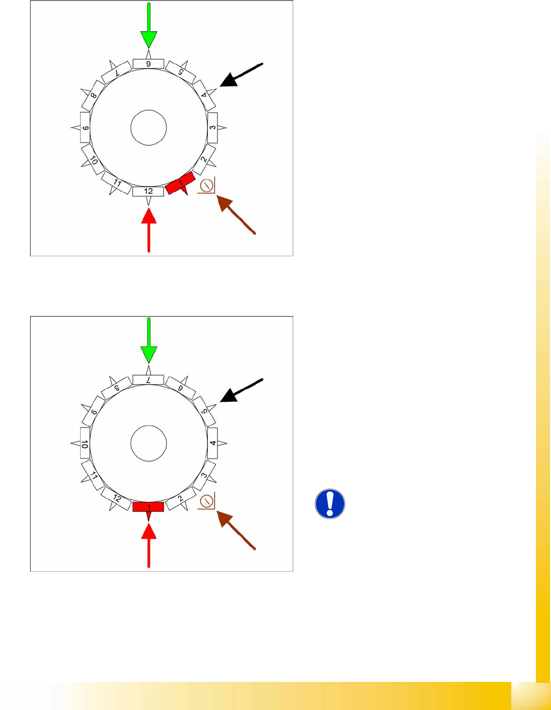
6.2.12 Picking Up Component 12
6.2.13 Placing Component 1
6-22: Picking up component 12
Star position 330°
Vision system: Optically centers component 6.
DP station: Rotates component 4 into its exact
placement angle.
Pickup/placement station: Picks up
component 12.
Communication with the changeover table:
Activate cutter.
Component sensor: During the next star cycle,
the component presence/component height
check is performed for segment 2.
6-23: Placing component 1
Star position 0°
Vision system: Optically centers component 7.
DP station: Rotates component 5 into its exact
placement angle.
Pickup/placement station: Places component
1.
Component sensor: During the next star cycle,
the component presence/component height
check is performed for segment 3.
This process is continued for the remaining
nozzles.
NOTE:
The machine learns a real placement
height for each placement position.This
is why placement of the first 15 or so
boards is significantly slower than
calculated by the setup optimization.
C&P6/12 Placement Heads
Placement Procedure Placing Component 6
Student Guide Advanced Level 1 SIPLACE D-Series
C&P6/12 Placement Heads EN 05/2007
6-20
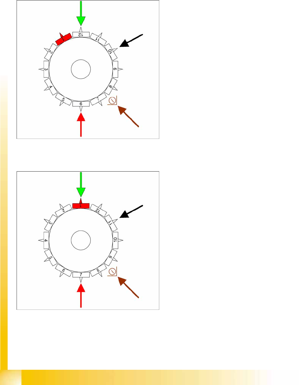
6.2.14 Placing Component 6
6.2.15 Placing Component 7
6-24: Placing component 6
Star position 150°
Vision system: optical centering of component
12
DP station rotation of component 10 into its
exact placement angle
Pickup/placement station: Place component 6
Component sensor: during the next star step,
the component presence/component height is
checked at segment 8.
6-25: Placing component 7
Star position 180°
Vision system: Optically centers a component
for another gantry (optical recognition of
individual gantries is no longer synchronized
against one another).
DP station: Rotates component 11 into its
exact placement angle.
Pickup/placement station: Places component
7.
Component sensor option: During the next
star cycle, the component presence/
component height check is performed for
segment 9.
C&P6/12 Placement Heads
Placing Component 12 Placement Procedure
Student Guide Advanced Level 1 SIPLACE D-Series
EN 05/2007 C&P6/12 Placement Heads
6-21
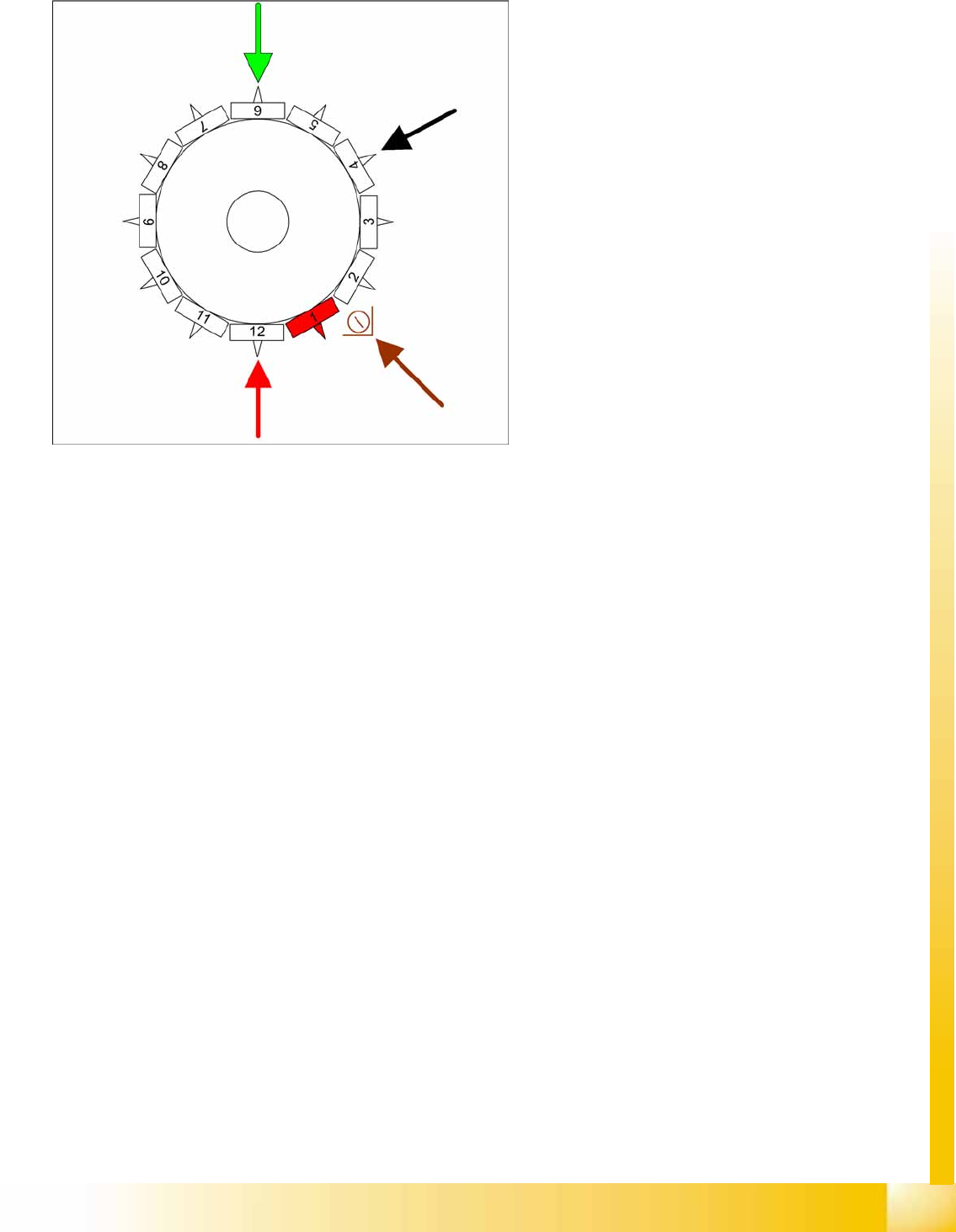
6.2.16 Placing Component 12
6.2.17 Pickup and Placement Cycle For the Next Components
After all the components of the first head cycle have been placed on the board, the gantry axes move
the placement head to the pickup position of the next pickup cycle.
The next pickup cycle is performed for components 13 - 24 (7 - 12 for C&P6).
The subsequent pickup cycles follow the same procedure. If necessary the machine performs repair
cycles.
6.2.18 Segment with a "Defect Component"
If the optical centering of a component (ident. error) or the pre-placement vacuum check (alternatively,
component recognition before placement) fails, the component will not be placed and will remain on the
nozzle.
The turning station still rotates this nozzle into the pickup angle for the new component, if this
segment is in the rotary position.
If this segment is in the pickup position:
The reject procedure is activated and
The X/Y gantry axes move to the reject position for that gantry,
The star rotates the segment into the reject position,
The component is rejected with an air blast,
The new component is taken up.
The rejected component is then placed during a repair cycle, performed after all the set placement cycles
for this placement head have been completed.
6-26: Placing component 12
Star position 330°
Vision system: optical centering of component
6 on other gantry
DP station rotation of nozzle 4 into the pickup
angle for the next placement cycle.
Pickup/placement station: Place component
12
Component sensor option: during the next star
step, the nozzle length is measured at
segment 2.