D-serie level 1 EN.pdf - 第104页
C&P6/12 Placement Heads Placement Procedure Optical Nozzle Query (Nozzle Scanning) S tuden t Guide Advanced Level 1 SIPLACE D-Series C&P6/12 Placement Heads EN 05/2007 6-24 6.2.24 Optical Nozzle Query (No zzle Sc…
C&P6/12 Placement Heads
Positioning into Placement Angle Placement Procedure
Student Guide Advanced Level 1 SIPLACE D-Series
EN 05/2007 C&P6/12 Placement Heads
6-23
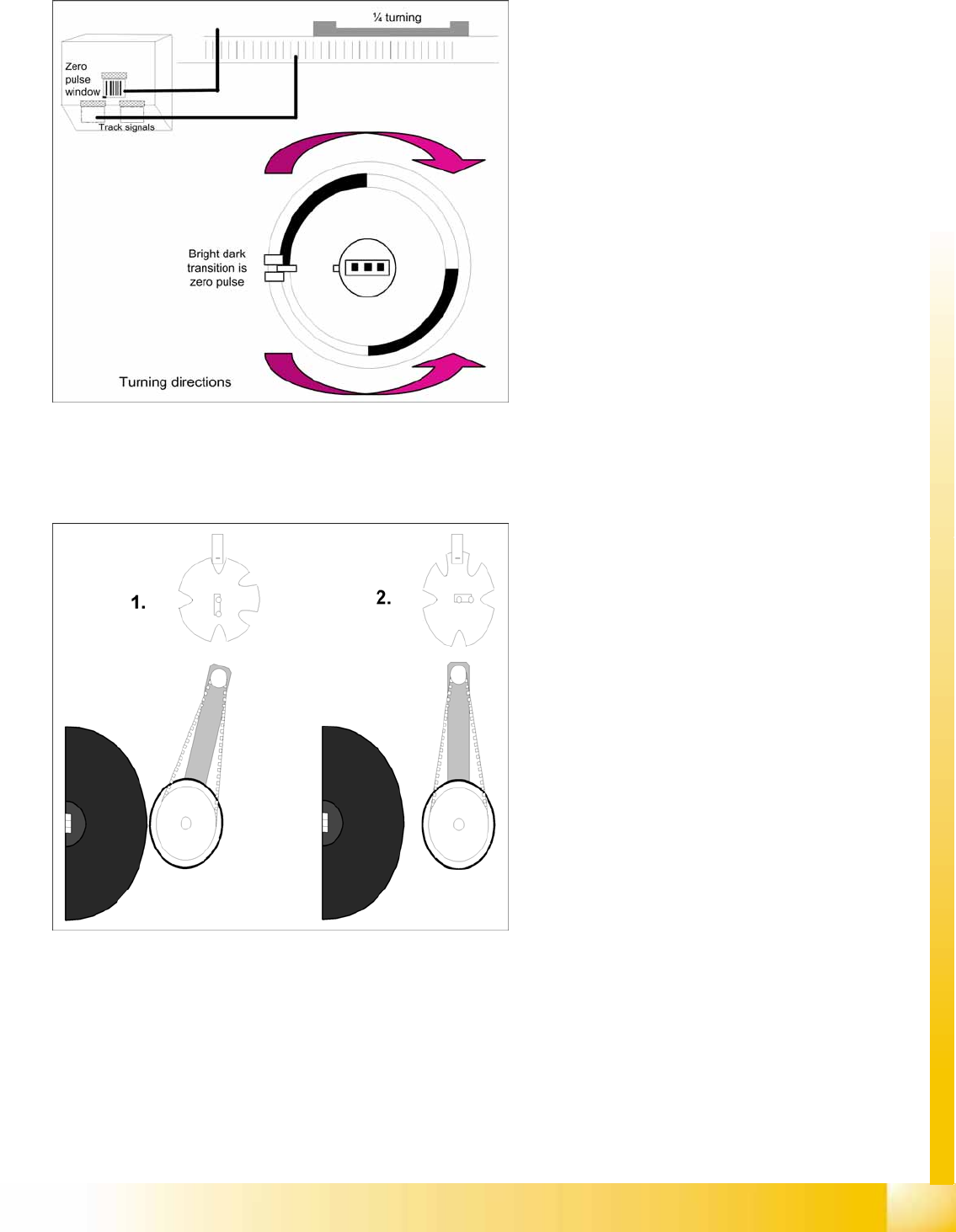
6.2.22 Positioning into Placement Angle
6.2.23 Detailed rotation of DP station, 3. Swivel Out
6-29: Detailed rotation process at DP station, positioning into placement
angle
When positioning begins, the actual position of
the axis is set to 0 by setting the position
counter of the DP axis to 0.
The DP drive is operated in relative positioning
mode.
The DP axis starts to move towards the target
position which is calculated from the station
calibration values, the line computer
programming values and the centering values
of the placement procedure.
An end position signal is emitted as soon as
the actual position deviation is within the
permitted tolerance.
6-30: Detailed rotation of DP station, 3. Swivel out
The command to start swiveling out is the end
position signal from DP positioning.
The DP drive is still located at the sleeve.
Diagram 1 shows the status when swiveled in.
The stepping motor is controlled by the light
barrier on the cam disk.
From its swiveled-in status, the stepping motor
rotates by 90° in a counterclockwise direction,
to swivel out.
Diagram 2 shows the status when swiveled
out.

C&P6/12 Placement Heads
Placement Procedure Optical Nozzle Query (Nozzle Scanning)
Student Guide Advanced Level 1 SIPLACE D-Series
C&P6/12 Placement Heads EN 05/2007
6-24
6.2.24 Optical Nozzle Query (Nozzle Scanning)
1. After placing the first board the nozzle query is activated:
– All nozzles listed for optical checking will be measured by the component camera (nozzles such
as 901, 904, 911, 914, 925).
– From SW 601, these can be found in the nozzle.lib.xml
– The optimum illumination technique and the appropriate algorithms enable SIPLACE Vision to
locate the exact outline of the nozzle type. In the case of deviations, a 'nozzle dirty' signal is
emitted at the station. This check is repeated until the operator has solved the problem with the
appropriate measures (replacement, cleaning).
SIPLACE Vision not only examines the outline but also the inner contours of the air inlet. In this
case, the station emits a 'vacuum system dirty' signal. (see above for solutions)
2. Due to the low component height, small nozzles may touch the soldering paste or adhesive if a
component has slipped.
3. The number of components per segment (number of head cycles), after the next nozzle query has
been performed, should be adjusted to the customer's process requirements. This test is always
performed after board processing has been completed.
Parallel to the nozzle query, the vacuum reference run for the placement head is repeated in order to
detect any changes in nozzle quality, during the placement process.
6.2.25 Air Blast Control During Placement
This function takes a programming option which was designed for the Twin and C&P20 heads and uses
it as follows for the C&P6/12 placement head, as a time control function.
Air blast control during placement with the C&P6/12 head
Entering "0" means: air blast valve will not be switched on. (Do not use!)
(1) Entering "1-50" means: air blast valve will be switched off before the stepping motor is started.
(Not recommended as the air blast is then too short to reliably place the component.
(2) Entering "51-150" means: air blast valve will be switched off at a 90° rotation of the stepping
motor.
(3) Entering "151-255" means: the air blast valve will be switched off when the light barrier is up or
when the stepping motor rotates by 180°.
No entry "----" (from conversion of 501/502 to 503) means: switching as in 3 (standard).
Air blast control for placing back (not rejecting) with the C&P6/12 head
(4) Entry and description as in (1)
(5) Entry and description as in (2)
(6) Entering "151-255" means: air blast valve will be switched off at a 180° rotation of the stepping
motor.
ATTENTION:
Do not use this function to save time. It will affect you placement reliability. Components could
be pushed up, for example.

C&P6/12 Placement Heads
Component Sensor Functional Description Placement Procedure
Student Guide Advanced Level 1 SIPLACE D-Series
EN 05/2007 C&P6/12 Placement Heads
6-25
6.2.26 Component Sensor Functional Description
The component sensor for the C&P12 head functions according to the shadow casting principle, to
determine the height of the component on the nozzle. This means that the nozzle shadow is compared
to the shadow caused by the nozzle with component.
Measurement is performed "on the fly", during star rotation.
Conditions for measurement:
The component sensor is fitted.
The component sensor is configured in SIPLACE Pro and SITEST.
The nozzle is longer than 12 mm and casts a shadow in the sensor.
The component on the nozzle is still within the 5mm measuring range
(
nozzle length in sensor + component height < 5 mm
).
The component has been selected for measurement in the component sensor (in order to measure
either the component presence or component height).
Measurement procedure:
Compare the "length of empty nozzle before pickup" with the "nozzle length during reference run".
Compare the component on the nozzle before placement (depends on operating mode) with the
"length of the empty nozzle before pickup".
After 350 head cycles, the "nozzle length during reference run" is measured again.
SIPLACE Pro Station software Measurement result
Advanced Component sensor presence check and
vacuum measurement
> nozzle length + component height -
component height tolerance
No vacuum Component sensor presence check
Component height
(component
thickness)
Component sensor height check > nozzle length + component height -
component height tolerance
and
< nozzle length + component height +
component height tolerance
Component presence check modes (SIPLACE Pro programming)